
Circuit Diagram
Index 1640
The inductance controlled switch circuit (2)
Published:2011/7/2 23:18:00 Author:Borg | Keyword: inductance controlled, switch circuit
Here is to introduce an inductance controlled switch circuit which is made of the CD4093 digital integrated circuit, it has almost the same functions and features with the separated element inducting control switch. This circuit consists of the inducting electrode plate A, square wave oscillator, trigger control circuit, detecting circuit and control executing circuit, see as the figure.
The inductance controlled switch circuitBy adjusting the volume of capacitor C4, the sensibility of the switch can be changed.Element selection R1~R3 are adopted with the 1/4W carbon film resistor or the metal film resistor. (View)
View full Circuit Diagram | Comments | Reading(816)
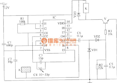
The inductance controlled switch circuit (4)
Published:2011/7/2 23:02:00 Author:Borg | Keyword: inductance controlled, switch circuit

The circuit that will be introduced can be used to control the lighting lamp and auto door, and it can also be used to burglarproof alarm. This circuit consists of the inducting electrode plate A, regulated diode VS, FET transistor VF, music integrated circuit IC, transistor V, relay K, diode VD, resistor R1 and R2, potentiometer RP and power supply switch S, etc, see as the figure.
The inductance controlled switch circuit By adjusting the potentiometer RP, the music time of the IC can be changed, so the lighting time of the lamp can be changed. (View)
View full Circuit Diagram | Comments | Reading(446)
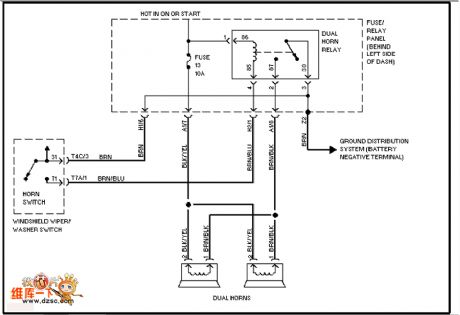
The Volkswagon loudspeaker circuit
Published:2011/6/30 22:55:00 Author:qqtang | Keyword: Volkswagon, loudspeaker
View full Circuit Diagram | Comments | Reading(450)
The inductance controlled switch circuit (1)
Published:2011/7/2 22:37:00 Author:Borg | Keyword: inductance control, switch circuit
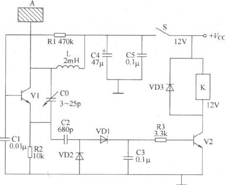
The following is to introduce an inductance controlled switch circuit (capacitance or approach control circuit) made of separated elements, when someone is getting close to the metal current inducting chip, the circuit is on and the load(indicator, alarm or lighting lamp, ventilator and so on) is working. The circuit consists of the inductance pole chip A, RF oscillator, RF detecting circuit and control executing circuit, see as the figure.
By adjusting the volume of C0, the staring/stopping TLV of the RF oscillator can be changed. (View)
View full Circuit Diagram | Comments | Reading(502)
The electric self-lock/interlock switch circuit
Published:2011/7/2 23:33:00 Author:Borg | Keyword: self-lock/interlock, switch circuit

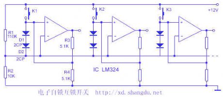
1.switch featuresThe core part of the switch is made of 4 op-amps LM324, with subtle design, each op-amp has two functions: the voltage comparator and the Schmidt trigger. The voltage range is large, and the stages can be adjusted, if it is added with a neutral gear, it can be the general reset, when the circuit cooperates with a digital circuit, they share a power supply, the input/output LEV conforms to the digital circuit connector LEV, as the input impedance of the op-amp is high, the input current of the switch is low. The touch switch, conductive rubber and film switch can be used as the key. (View)
View full Circuit Diagram | Comments | Reading(1040)
TWL2213 Lithium ion battery charging process circuit
Published:2011/7/1 1:25:00 Author:TaoXi | Keyword: Lithium ion battery, charging, process

View full Circuit Diagram | Comments | Reading(513)
The electric ganged switch switch
Published:2011/7/2 23:41:00 Author:Borg | Keyword: electric, ganged switch
View full Circuit Diagram | Comments | Reading(532)
Vizi saloon car headlight, rear foglight and front foglight circuit
Published:2011/7/1 1:28:00 Author:TaoXi | Keyword: Vizi, saloon car, headlight, rear foglight, front foglight
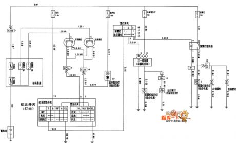
The Vizi saloon car headlight, rear foglight and front foglight circuit is as shown in the figure:
(View)
View full Circuit Diagram | Comments | Reading(409)
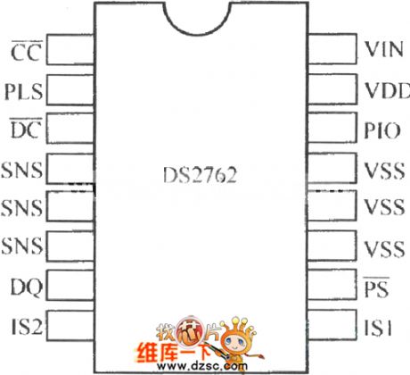
DS2762 pin arrangement circuit
Published:2011/7/1 1:28:00 Author:TaoXi | Keyword: pin arrangement
View full Circuit Diagram | Comments | Reading(467)
The ceiling lamp control switch circuit (1)
Published:2011/7/2 23:51:00 Author:Borg | Keyword: ceiling lamp, control switch circuit

Usually, there are many bulbs in a ceiling lamp, when the power is on, all the bulbs are lighting, if the ceiling lamp is working for a long time, it will be energy-consuming. The ceiling lamp control circuit that will be introduced can choose to control the number of the lighting bulb in 8 bulbs, according to the need. The switch circuit consists of the power supply circuit and control circuit, which is shown in the figure.
Element selection R1 is adopted with the 1/2W metal film resistor; R2~R12 can be the 1/4W carbon film resistor or metal film resistor. (View)
View full Circuit Diagram | Comments | Reading(546)
The ceiling lamp control switch circuit (5)
Published:2011/7/3 0:03:00 Author:Borg | Keyword: ceiling lamp, control switch circuit

This circuit consists of the power supply circuit, the trigger control circuit A and the trigger control circuit B, see as the figure.
If K1 or K2 can't be locked, then the power should be supplied independently.Element selection R1 is the 1/2W metal film resistor; R2~R6 are made of the 1/4W carbon film resistor or the metal film resistor. C1 is the CBB capacitor whose withstand voltage higher than 400V; C2 and C3 are made of the 25V aluminum electrolytic resistor. VD1~VD6 are all made of the 1N4007 silicon rectifier diode. VS is the 1N4742(1W、12V) silicon rectifier diode. (View)
View full Circuit Diagram | Comments | Reading(497)
Push-twist circuit uses the complementary transistor and the CMOS driver stage
Published:2011/7/1 1:30:00 Author:TaoXi | Keyword: Push-twist circuit, complementary transistor, CMOS driver stage

Figure: the Push-twist circuit uses the complementary transistor and the CMOS driver stage
(View)
View full Circuit Diagram | Comments | Reading(681)
SIPMOS control circuit uses the transformer potential isolation
Published:2011/7/1 1:31:00 Author:TaoXi | Keyword: SIPMOS, control circuit, transformer, potential isolation

Figure: SIPMOS control circuit uses the transformer potential isolation
(View)
View full Circuit Diagram | Comments | Reading(552)
MAXl898 single Li+ battery linear charger circuit
Published:2011/7/1 1:33:00 Author:TaoXi | Keyword: single, Li+ battery, linear charger

View full Circuit Diagram | Comments | Reading(541)
Southeast Freeca engine circuit
Published:2011/7/1 1:34:00 Author:TaoXi | Keyword: Southeast, Freeca, engine circuit
The Southeast Freeca engine circuit is as shown in the figure:
(View)
View full Circuit Diagram | Comments | Reading(417)
Vizi starting motor and generator circuit
Published:2011/7/1 1:36:00 Author:TaoXi | Keyword: Vizi, starting motor, generator
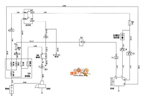
The Vizi starting motor and generator circuit is as shown in the figure:
(View)
View full Circuit Diagram | Comments | Reading(592)
SIPMOS transistor complementary Darlington control circuit
Published:2011/7/1 1:37:00 Author:TaoXi | Keyword: SIPMOS, transistor, complementary Darlington, control circuit

Figure:SIPMOS transistor complementary Darlington control circuit
(View)
View full Circuit Diagram | Comments | Reading(611)
The ceiling lamp control switch circuit (4)
Published:2011/7/3 0:16:00 Author:Borg | Keyword: ceiling lamp, control switch circuit

Here is to introduce a ceiling lamp control switch circuit which consists of the CD4518 digital integrated circuit, it can control each line of bulbs. The circuit consists of the power supply circuit, trigger control circuit and control executing circuit, see as the figure.
Element selectionR1~R5 and R7~R9 are made of the 1/4W carbon film resistor or the metal film resistor; R6 is the 1/2 metal film resistor. C1 and C2 are made of the monolithic capacitor or the dacron capacitor; C3 is the aluminum electrolytic resistor whose withstand voltage is 16V. (View)
View full Circuit Diagram | Comments | Reading(484)
The ceiling lamp control switch circuit (3)
Published:2011/7/3 0:26:00 Author:Borg | Keyword: ceiling lamp, control switch

Here is to introduce a ceiling lamp control circuit which is in 2-line control system, the control circuit is installed in the lampshade, and it can control the two states of the lamp through the switch. The circuit consists of the power supply circuit and trigger control circuit, see as the figure.
Element selection Both R1 and R4 are the 1/2W metal film resistor; R2, R3 and R5~R8 are all made of 1/4W metal film resistor; C1 is the aluminum electrolytic resistor whose withstand voltage is 25V; C2 is the aluminum electrolytic resistor whose withstand voltage is over 16V. (View)
View full Circuit Diagram | Comments | Reading(492)
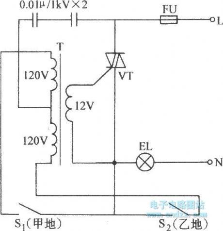
The ceiling lamp control switch circuit (6)
Published:2011/7/3 0:36:00 Author:Borg | Keyword: ceiling lamp, control switch
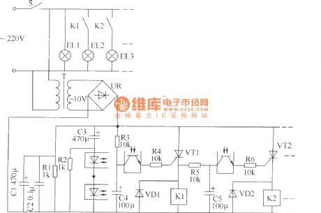
The ceiling lamp control switch circuit consists of the power supply circuit and the control circuit, see as the figure.
Element selection R1 is the 1/2W metal film resistor, R2~R6 are the 1/4W metal film resistors or carbon film resistor; C1 and C3~C5 are all made of the the aluminum electrolytic resistor whose withstand voltage is 16V; C2 is the monolithic capacitor. VD1 and VD2 are both made of the 1N4007 silicon diode. UR is the rectifier bridge of 1A and 50V. VT1 and VT2 are both the MCR100-6 thyristor. K1 and K2 are both the 9V DC relay of JZC-23F. (View)
View full Circuit Diagram | Comments | Reading(488)
| Pages:1640/2234 At 2016211622162316241625162616271628162916301631163216331634163516361637163816391640Under 20 |
Circuit Categories
power supply circuit
Amplifier Circuit
Basic Circuit
LED and Light Circuit
Sensor Circuit
Signal Processing
Electrical Equipment Circuit
Control Circuit
Remote Control Circuit
A/D-D/A Converter Circuit
Audio Circuit
Measuring and Test Circuit
Communication Circuit
Computer-Related Circuit
555 Circuit
Automotive Circuit
Repairing Circuit