Control Circuit
The ceiling lamp control switch circuit (6)
Published:2011/7/3 0:36:00 Author:Borg | Keyword: ceiling lamp, control switch | From:SeekIC

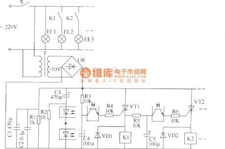
The ceiling lamp control switch circuit consists of the power supply circuit and the control circuit, see as the figure.
Element selection R1 is the 1/2W metal film resistor, R2~R6 are the 1/4W metal film resistors or carbon film resistor; C1 and C3~C5 are all made of the the aluminum electrolytic resistor whose withstand voltage is 16V; C2 is the monolithic capacitor. VD1 and VD2 are both made of the 1N4007 silicon diode. UR is the rectifier bridge of 1A and 50V. VT1 and VT2 are both the MCR100-6 thyristor. K1 and K2 are both the 9V DC relay of JZC-23F.
Reprinted Url Of This Article:
http://www.seekic.com/circuit_diagram/Control_Circuit/The_ceiling_lamp_control_switch_circuit_6.html
Print this Page | Comments | Reading(3)

Article Categories
power supply circuit
Amplifier Circuit
Basic Circuit
LED and Light Circuit
Sensor Circuit
Signal Processing
Electrical Equipment Circuit
Control Circuit
Remote Control Circuit
A/D-D/A Converter Circuit
Audio Circuit
Measuring and Test Circuit
Communication Circuit
Computer-Related Circuit
555 Circuit
Automotive Circuit
Repairing Circuit
Code: