
Circuit Diagram
Index 1635
Electric welding machine no load electricity saver 10
Published:2011/6/30 21:38:00 Author:Nicole | Keyword: electric welding machine, electricity saver

The electric welding machine no load electricity saver circuit is composed of detection circuit and energy saving control circuit, it is shown in the figuer 8-14.
The detection circuit is made of current transformer TA, diodes VD1, VD2, transistor V, bridge rectifiers UR, filter capacitor C3.
The energy saving control circuit consists of resistors R1, R2, capacitors C1, C2, steady voltage diodes VS1, VS2, thyristor VT, diode VD3, relay K and AC contactor KM.
The electric welding machine transformer is composed of knife switch Q, fuse F.
(View)
View full Circuit Diagram | Comments | Reading(3339)
TMM41256P DRAM Integrated Circuit Diagram
Published:2011/7/3 2:35:00 Author:Vicky | Keyword: DRAM Integrated Circuit

TMM41256P is a dynamic RAM integrated circuit produced by Toshiba. TMM41256P, together with T6668 constitutes the voice mail system of a dictaphone.
1. Functions and datum of pins
16 pins of IC TMM41256P are in dual-in-line packages.
2. Typical applied circuit
As shown in the picture, typical applied circuit of TMM41256P is identical with IC T6668.
Note: Domestic model no. D41256 is the same with IC TMM41256P, therefore the two part no. can be replaced by each other directly. (View)
View full Circuit Diagram | Comments | Reading(1083)
Electric welding machine no load electricity saver 8
Published:2011/6/30 21:30:00 Author:Nicole | Keyword: electric welding machine, electricity saver
The electric welding machine no load electricity saver circuit is composed of knife switch Q, relays K1, K2, intermediate relay KA, AC contactor KM, time relay KT, reed switch SA, diodes VD1, VD2, indication light HL, resistor R, capacitors C1-C3, potentiometers RP1, RP2 and electric welding machine transformer T, it is shown in the figure 8-12.
When KM pulls in, but it is not welded, the induced voltage which produced by the both sides of T's secondary winding is rectified by VD2 and then it is added to K2, K2 is pulled in, K2's normally open contact is turned on, KT pulls in and it starts to timing.
(View)
View full Circuit Diagram | Comments | Reading(2137)
Electric welding machine no load electricity saver 7
Published:2011/6/30 21:10:00 Author:Nicole | Keyword: electric welding machine, electricity saver

The electric welding machine no load electricity saver circuit is composed of control power transformer T1, intermediate relay KA, relay KT, AC contactor KM, potentiometer RP and indication light HL1, HL2, it is shown in the figure 8-11.
After knife switch Q is turned on, T1 works, power indication light HL1 lights. When welding, below, intermediate relays KA pull in, the normally open contact KA1, KA2 are turned on, then KKM's normally open contact KM1, KM2 are turned on, the normally closed contact KM3 and KM4 are cut off, it works, it shows it can do welding.
(View)
View full Circuit Diagram | Comments | Reading(1518)
Darlington Type Phototransistor Optical Triggered Switch Application Circuit
Published:2011/7/3 6:36:00 Author:Robert | Keyword: Darlington, Phototransistor, Optical Triggered Switch, Application

The picture shows the darlington type phototransistor optical triggered switch application circuit.
Because of using the darlington type phototransistor and operational amplifier, the very weak light can flip the circuit. If the positions of R1 and phototransistor are be reversed, or the positions of the operational amplifier's out-phase and in-phase input ports are reversed, the circuit can modified to be triggered opening by the dark. (View)
View full Circuit Diagram | Comments | Reading(1220)
Electric welding machine no load electricity saver 6
Published:2011/6/30 21:00:00 Author:Nicole | Keyword: electric welding machine, electricity saver
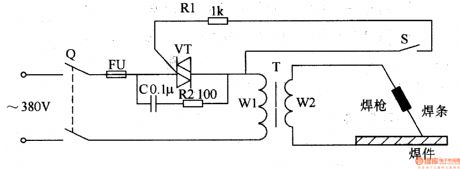
The electric welding machine no load electricity saver circuit is composed of knife switch Q, fuse FU, capacitor C, resistors R1, R2, thyristor VT, electric welding machine transformer T and trigger switch S, it is shown in the figure 8-10.
When knife switch Q is turned on, 380V AC voltage is added to T's circuit by Q(the circuit is made of FU, VT, C, R2 and winding W1). When trigger switch S is not turned on, VT is in off state, C, R2 are connected into the circuit, then the electric welding machine is in electricity saving state, the current which flows T's loop is smaller.
(View)
View full Circuit Diagram | Comments | Reading(3590)
Semiconductor transistor basic amplifying circuit
Published:2011/7/3 20:58:00 Author:Christina | Keyword: Semiconductor, transistor, basic amplifying

When the amplifier circuit is amplifying the signal, it always has two electrodes to be used as the input port of the signal, and there are two electrodes to be used as the output port. There are three kinds of circuit according to the connection mode between the three electrodes of the semiconductor transistor and the input & output terminals: the common emitter circuit, the common base circuit and the common collector circuit. The connection modes of these circuits are as shown in figure.
Figure 1 The three connection modes of the semiconductor transistor basic amplifier circuit
(View)
View full Circuit Diagram | Comments | Reading(557)
Electric welding machine no load electricity saver 5
Published:2011/6/30 20:52:00 Author:Nicole | Keyword: electric welding machine, electricity saver

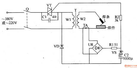
The electric welding machine no load electricity saver circuit is composed of current detection control circuit and electricity saving control circuit, it is shown in the figure 8-9.
The current detection control circuit is made of current transformer TA, bridge rectifiers UR, resistor R1, steady voltage diode VS, capacitor C2 and diode VD.
When the welding rod needs to change or stop transitorily for some reasons, C2 discharges to VT's gate passes through VS and R2, then VT keeps on. After C2 finishes discharging, VT is off, C1 is connected into another loop of T, the electric welding machine is in saving state again.
(View)
View full Circuit Diagram | Comments | Reading(3435)
Samsung 173B LCD DC/DC Convertor Circuit
Published:2011/7/1 0:27:00 Author:Joyce | Keyword: Samsung , 173B , LCD , DC/DC , Convertor

Samsung 173B LCD DC/DC convertor circuit is shown as follows.
Samsung 173B LCD DC/DC Convertor Circuit (View)
View full Circuit Diagram | Comments | Reading(568)
Thyristor ladder wave inverter circuit
Published:2011/7/3 20:25:00 Author:Christina | Keyword: Thyristor, ladder wave, inverter circuit

The circuit is as shown, the six taps of the transformer T is connected with the unidirectional thyristors VS1~VS6 to form the thyristor inverter main circuit.
By the function of the trigger control circuit, the action program of the circuit is as shown: the circuit makes the thyristor VS1 to conduct for 30°, then it makes the VS2 to conduct for 30°, then makes the VS3 to conduct for 60°, during this time the thyristors cuts off by the induced voltage which is produced by the transformer winding. After the VS3 cuts off, the circuit will cut off the VS2 to finish the output of the half cycle ladder wave.
Thyristor ladder wave inverter circuit (View)
View full Circuit Diagram | Comments | Reading(5086)
Electric welding machine no load electricity saver 4
Published:2011/6/30 20:40:00 Author:Nicole | Keyword: electric welding machine, electricity saver

The electric welding machine no load electricity saver circuit is composed of +12V power supply circuit, current detection control circuit, dalay control circuit and control implement circuit, it is shown in the figure 8-8.
The +12V power supply circuit is made of knife switch Q, fuse FU, power transformer T1, bridge rectifiers UR and filter capacitor C2.
The dalay control circuit consists of resistor R7, capacitors C3, C4, time base integrated circuit IC, relay K, AC contactor KM and diode VD5.
T2 is electric welding machine transformer, the energy saving circuit is composed of R1, R8, C1.
(View)
View full Circuit Diagram | Comments | Reading(4619)
ED-9515 Coding Integrated Circuit
Published:2011/7/3 6:23:00 Author:Robert | Keyword: Coding, Integrated


The ED-9515 is a coding IC which is used in the communication equipments, car remote-control anti-theft system and other fields.
1.Its pin's functions.
The ED-9515 IC uses 18-pin dual inline package and its pin's function and data is listed in table 1.
The table 1 shows the ED-9515 IC's pin's functions and data.
It should be noted that this voltage has relations with the K1-K8 coding. When the switch is closed, this pin's voltage is 4.8V. When the switch is closed this pin's voltage is 0V.
2.Typical application circuit.
The coding circuit typical application circuit composed of ED-9515 IC is shown in picture 1.
The picture 1 shows the ED-9515 IC's typical application circuit.
It is noted that the ED9515 can also be used as decoder which can make up a decoding circuit. (View)
View full Circuit Diagram | Comments | Reading(706)
EM91403CK Communication Single-Chip Micro-Computer Integrated Circuit
Published:2011/7/3 6:06:00 Author:Robert | Keyword: Communication, Single-Chip, Micro-Computer, Integrated


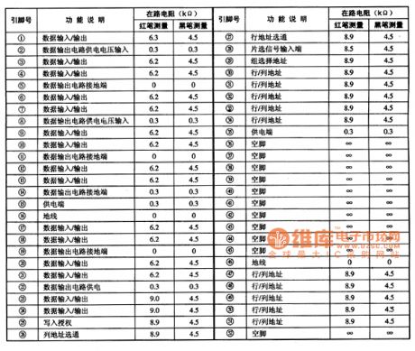
The EM91403CK is a communication single-chip micro-computer IC which is widely used in many kinds of caller ID telephones.
1.Its pin's functions.
The EM91403CK IC uses 22-pin dual inline package and its pin's functions are listed in table 1.
The table 1 shows the EM91403CK IC's pin's functions.
2.Typical application circuit.
The dialing control system typical application circuit composed of EM91403CK IC is shown in picture 1.
The picture 1 shows the EM91403CK IC's typical application circuit. (View)
View full Circuit Diagram | Comments | Reading(1547)
2CU silicon photosensitive diode appearance circuit
Published:2011/7/3 21:18:00 Author:Christina | Keyword: silicon, photosensitive diode, appearance circuit
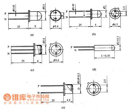
The 2CU silicon photosensitive diode is in the sealed shell package, there is the optical lens or flat glass window on the top of the package. The 2CU silicon photosensitive diode can be used to receive the light and also can be used in the photo-electric conversion automatic control instrument, the trigger, the photoelectric coupler, the encoder and decoder, the characteristics identification circuit, the process control circuit and the laser receiving circuit.
The 2CU101/201 silicon photosensitive diode can be used to receive the light signal of the fibre-optical communication. The appearance structure is as shown in the figure.
2CU silicon photosensitive diode appearance circuit (View)
View full Circuit Diagram | Comments | Reading(571)
CD4541 nickel-cadmium battery automatic charger circuit
Published:2011/6/20 6:36:00 Author:chopper | Keyword: nickel-cadmium battery, automatic charger circuit

This circuit is designed for number 5,number 7 nickel-cadmium battery especially,and it has features of automatic charging and constant-current charging.The circuit is shown as follows.The circuit will begin to run as soon as the power supply is connected.The inner counter is responsible for counting the oscillator to a full count,and at this moment,the output level of foot ⑧ of IC1 will return to stop counting.For instance,foot ⑩ is connected with high level,and the food ⑧ will return when the counter is full,then it will count again,and return when it is full,and so on and so on.
(View)
View full Circuit Diagram | Comments | Reading(4090)
A45L9332F dynamic memory integrated circuit
Published:2011/7/3 21:32:00 Author:Christina | Keyword: dynamic memory, integrated circuit
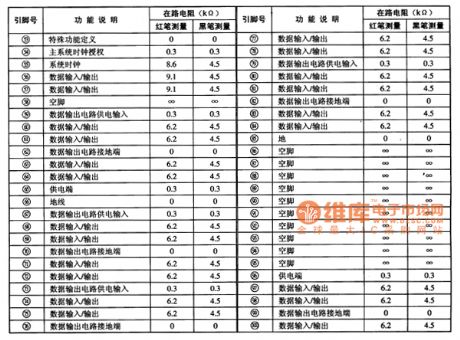
The A45L9332F is designed as one kind of 16777216-bit synchronous high data rate dynamic memory integrated circuit that can be used in the ChangHong HP series rear projection color TVs.
1.Features
The A45L9332FF uses the CMOS technology, and it is accurately controlled by the system clock to finish the storage work of data. The internal storage space is divided into two groups, every group is 256Kx32bit. This ciruit has the system clock circuit, the data input/output interface circuit, the line & row address selective passing circuit, the line & row address unit, the data circuit power supply system and other subsidiary function circuits.
2.Pin functions and data
The A45L933FF uses the 100-pin square flat package structure, the pin functions and data is as shown in table 1.
Table 1 The pin functions and data of the A45L9332F
(View)
View full Circuit Diagram | Comments | Reading(489)
2DU photosensitive diode application circuit
Published:2011/7/3 21:36:00 Author:Christina | Keyword: photosensitive diode, application circuit
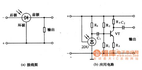
The 2DU photosensitive diode application circuit has three pins: the front pole, the rear pole and the circumpolar. The connection modes and the application circuits are as shown in the figure.
Figure: 2DU photosensitive diode application circuit (View)
View full Circuit Diagram | Comments | Reading(677)
cellphone lithium ion battery charger circuit of LM317
Published:2011/6/20 6:37:00 Author:chopper | Keyword: cellphone, lithium ion battery, charger circuit

View full Circuit Diagram | Comments | Reading(4081)
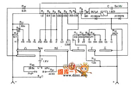
MF88 multimeter circuit diagram
Published:2011/6/24 4:40:00 Author:Nicole | Keyword: multimeter
View full Circuit Diagram | Comments | Reading(772)
(CD4069) shine type logical pen circuti of gate circuit
Published:2011/6/20 6:39:00 Author:chopper | Keyword: shine type, logical pen, gate circuit

View full Circuit Diagram | Comments | Reading(628)
| Pages:1635/2234 At 2016211622162316241625162616271628162916301631163216331634163516361637163816391640Under 20 |
Circuit Categories
power supply circuit
Amplifier Circuit
Basic Circuit
LED and Light Circuit
Sensor Circuit
Signal Processing
Electrical Equipment Circuit
Control Circuit
Remote Control Circuit
A/D-D/A Converter Circuit
Audio Circuit
Measuring and Test Circuit
Communication Circuit
Computer-Related Circuit
555 Circuit
Automotive Circuit
Repairing Circuit