
Circuit Diagram
Index 1639
OPA604 High Performance and Small Power Audio Amplifier Circuit
Published:2011/6/24 13:21:00 Author:Michel | Keyword: High Performance, Small Power, Audio, Amplifier Circuit

The above picture is high performance and small power audio power amplifier circuit.This circuit's former level uses the mosfet hi-fi op-amp OPA604 and next level adopts high-speed buffer BUF634 and voltage series negative feedback is used between two levels amplifiers. This circuit voltage magnification depends on two resistances (5kΩ and 250Ω)of feedback branchs and its value is l+5kΩ/250Ω≈21 times.BUF634 is high-speed buffers and itsinternal structure simplified circuit is shown in figure (b). (View)
View full Circuit Diagram | Comments | Reading(1764)
TV remote control 01 circuit
Published:2011/7/2 4:35:00 Author:John | Keyword: TV remote control

View full Circuit Diagram | Comments | Reading(548)
TV remote control 02 circuit
Published:2011/7/2 4:36:00 Author:John | Keyword: TV remote control

View full Circuit Diagram | Comments | Reading(626)
electrical equipment overheating "brakes" voice alarming circuit
Published:2011/7/2 2:00:00 Author:John | Keyword: electrical equipment

The figure shows the electrical equipment analog voice alarming circuit. It consists of overheating electronic switch, controlled multi-vibrator, analog voice circuits, audio amplifier circuit and AC buck rectifier circuit. The controlled multi-vibrator consists of 555, R2, R3 and Cl and so on. Its multivibrator frequency is that the icon parameter oscillation period To (= 1/fo) is equal to 10s. (View)
View full Circuit Diagram | Comments | Reading(500)
Southeast Lioncel engine multi-point injection (MPI) Y with the computer system circuit
Published:2011/7/2 2:02:00 Author:John | Keyword: computer system, engine, multi-point injection
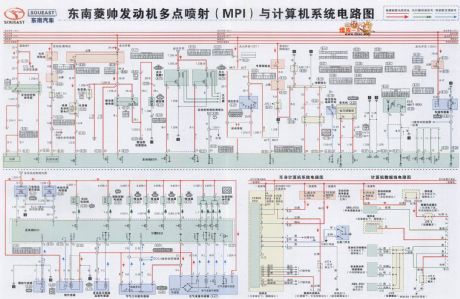
View full Circuit Diagram | Comments | Reading(1245)
MAX1501 charger circuit
Published:2011/7/2 1:50:00 Author:John | Keyword: charger

MAX1501 is a new generation of rechargeable chip. MAX1501 is used to simplify the design of the charger. MAX1501 can be set as the single cell Li-Ion battery charging controller and can also be set as charging controller with three nickel cadmium batteries and Nickel metal hydride battery in series. MAX1501 charger circuit is as shown.
(View)
View full Circuit Diagram | Comments | Reading(1064)
Electronic energy saving lamp (3)
Published:2011/6/30 2:08:00 Author:Ecco | Keyword: Electronic, energy saving, lamp

In the circuit shown as the chart, T uses E5 ferrite core with Φ0.2mm high-intensity polyester wire, and L1, L2 have about 12 to 30 turns, and L3 has 200 turns; RT uses RTC thermistor, such as MZ11B, MZ64 types.
(View)
View full Circuit Diagram | Comments | Reading(724)
The DC/AC double purpose dark room safelight
Published:2011/7/2 2:25:00 Author:Borg | Keyword: double purpose, dark room safelight


This DC/AC double purpose dark room safelight has the function of pointless auto converting switch. It is adopted with orange LED.
When the power is normally supplied, the AC 220V is rectified by the transformer, filtered by the capacitor, and then is turned into a 4V or so DC (it's 5V when it is in empty load). As the voltage of the battery in the machine is 3V, the diode D is conducting and powered by the rectifier power supply. As the BG emitter LEV is lower than the basic LEV, therefore, BG is blocked, the battery E is cut off automatically and there is no current out.When the power is off, the LEV of BG emitting pole is higher than the basic pole LEV. (View)
View full Circuit Diagram | Comments | Reading(935)
The simple touching switch
Published:2011/7/2 3:27:00 Author:Borg | Keyword: simple touching switch

In experiments, the writer found that the single-way SCR (MCR100-8) control pole can be conducted by hand touch without any forward voltage. Therefore, the writer designed a simple touching switch, whose circuit is shown in the figure.
Just by touching the metal chip, SCR1 is conducting, so the load is getting power and working; by touching the metal chip, the switch is off and SCR2 is conducting, the relay 1 is getting power and working, K is cut off, the load loses power, after SCR2 is broken down, the capacitor is discharging power to relay J, which keeps the relay close about 4s. (View)
View full Circuit Diagram | Comments | Reading(865)
The simple power-off self-lock circuit
Published:2011/7/2 3:14:00 Author:Borg | Keyword: power-off, self-lock
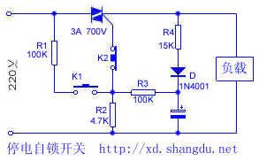
When the grid is supplying power normally, it is like an ordinary switch. By pressing K1, the 220V AC is distributed to the dual-way SCR as the trigger voltage, which makes the SCR conducting. When the SCR is conducting, during the positive half-cycle period of the power supply, a little current is charging C through R4 and D, at the same time, after being distributed by R3 and R2, it charges the SCR; in the passive half-cycle, C discharges R3 and R2 and then triggers the SCR, so that the SCR keeps conducting, which makes sure the load work normally. Once the grid was power-off suddenly, C would be discharging through R3 and R2.
(View)
View full Circuit Diagram | Comments | Reading(757)
The simple electric water tag circuit
Published:2011/7/2 3:01:00 Author:Borg | Keyword: electric water tag

1.working principle The circuit is shown in the figure. PC is a photoelectric coupler, whose feature is that the input and output is fully separated, so it is safe. S is the key switch of step type. The 220V mains is half-wave rectified by the diode D, filtered by capacitor C, and then distributed by R4 and R5, finally, it becomes an output DC voltage of about 10V which is added on the C pole of the triode in the PC. Usually, S is opened, the LED in the PC has no current and is not glowing, the light dependent triode is blocked, the transistor V is blocked. (View)
View full Circuit Diagram | Comments | Reading(493)
The simple and useful 3-key interlock electric switch circuit
Published:2011/7/2 4:16:00 Author:Borg | Keyword: 3-key interlock, electric switch
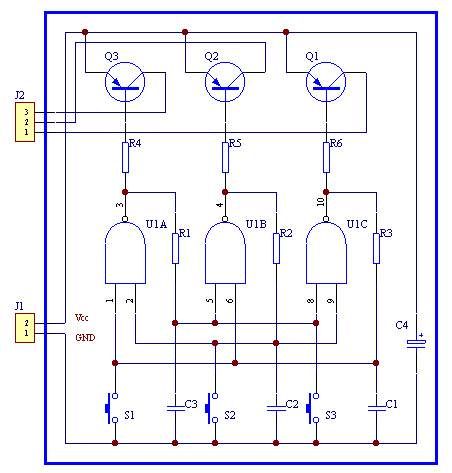
The structure of the circuit is simple, a channel is opened by pressing a corresponding key, meanwhile the other 2 channels are closed. The contactor shake does not affect the working of the circuit, so the anti-disturbance ability is good. If the drive triode in the back was removed, the static power consumption of the circuit would almost 0. If the key was removed, the circuit would be the pulse control.
(View)
View full Circuit Diagram | Comments | Reading(713)
The simple self-lock switch circuit
Published:2011/7/2 2:38:00 Author:Borg | Keyword: self-lock switch

See as the figure, before AN is pressed, SCR1 is blocked, the relay or contactor is still, which is equal to OFF state. When AN is pressed, with the help of R1,AN and VD1,the 12V voltage provide for SCR1 with trigger current which makes it conducting, so K gets power and the contactor is connected with the load and gets into work. As the voltage on the two terminals of the capacitor can't mutate, so SCR2 is not conducting when AN is pressed, the current is charged to C by R3 and VD2. If AN is pressed again, the voltage on C is becoming the trigger voltage of SCR2, which makes SCR2 conducting when AN is blocked. (View)
View full Circuit Diagram | Comments | Reading(563)
An object approaching switch circuit
Published:2011/7/2 2:28:00 Author:Borg | Keyword: switch circuit

View full Circuit Diagram | Comments | Reading(492)
The simple 2-terminal source free electric energy saving switch circuit
Published:2011/7/2 3:40:00 Author:Borg | Keyword: 2-terminal, source free, energy saving switch

By pressing S, the 220V AC current is charging C through V5 after it is rectified, when the voltage on the capacitor is higher than the trigger voltage of the single way SCR control pole, the SCR is triggered and conducting, and the bulb is lighting. After S is released, the electricity of the capacitor is discharging through resistor R, which keeps the single-way SCR conducting, when the time reaches the set time (the lighting time of this circuit parameter is from 1 to 2min), the single-way SCR is cut off when the current is lower than the maintaining current, the bulb is cut off. (View)
View full Circuit Diagram | Comments | Reading(3474)
The 3 additional circuits of relays
Published:2011/7/2 4:05:00 Author:Borg | Keyword: additional circuits, relays

The relay is a common element in electronic circuit, which often consists of the electric switch drive circuit formed by the transistor, relay and others, and other circuits that can change the working features of the relay or fulfill protection function. The additional circuits of the relay has 3 pattens:
1. The relay parallel RC circuit: the circuit type is shown in figure 1, and it is often used in the circuits that the regulated working voltage is lower than the power supply voltage. When the circuit is closed, the current in the relay coil is increaseing. (View)
View full Circuit Diagram | Comments | Reading(466)
The astable circuit of improving the input waveform
Published:2011/7/3 20:52:00 Author:Borg | Keyword: astable circuit, waveform
View full Circuit Diagram | Comments | Reading(525)
The collecting basic coupling single steady circuit
Published:2011/7/2 4:36:00 Author:Borg | Keyword: single steady circuit

View full Circuit Diagram | Comments | Reading(458)
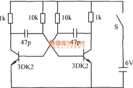
The high-frequency and astable state circuit
Published:2011/7/2 4:19:00 Author:Borg | Keyword: high-frequency, astable state
View full Circuit Diagram | Comments | Reading(539)
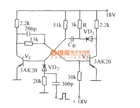
The high-speed single steay circuit (1)
Published:2011/7/2 4:29:00 Author:Borg | Keyword: high-speed, single steay circuit
View full Circuit Diagram | Comments | Reading(468)
| Pages:1639/2234 At 2016211622162316241625162616271628162916301631163216331634163516361637163816391640Under 20 |
Circuit Categories
power supply circuit
Amplifier Circuit
Basic Circuit
LED and Light Circuit
Sensor Circuit
Signal Processing
Electrical Equipment Circuit
Control Circuit
Remote Control Circuit
A/D-D/A Converter Circuit
Audio Circuit
Measuring and Test Circuit
Communication Circuit
Computer-Related Circuit
555 Circuit
Automotive Circuit
Repairing Circuit