
Circuit Diagram
Index 1623
The adjustable polarity inverting power supply composed of MAX764
Published:2011/6/25 5:27:00 Author:Borg | Keyword: adjustable polarity, inverting power supply

1.The stable output detect point; 8.switch pipe leakage pole exit; 2.feedback terminal; 7.positive power supply; 3.turn-off mode controller; 6.positive power supply; 4.reference voltage output terminal; 7.public ground connector. (View)
View full Circuit Diagram | Comments | Reading(716)
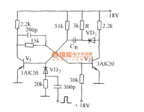
The high-speed single steady circuit (1)
Published:2011/7/4 4:03:00 Author:Borg | Keyword: high-speed, single steady circuit
View full Circuit Diagram | Comments | Reading(420)
The TDA2030A power amplifier circuit
Published:2011/6/25 5:28:00 Author:Borg | Keyword: power amplifier
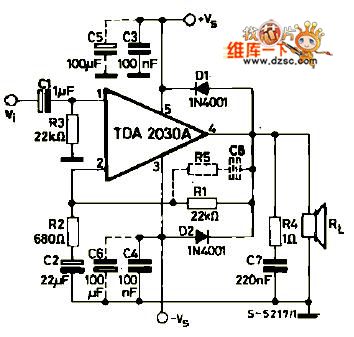
TDA2030A is the power amplifier circuit produced by Telefunken, which is V type 5-pin in-line plastic package.
Circuit features:1. Few external components; 2. Large output power, Po=18W(RL=4Ω); 3. it is in super small package(TO-220), which can raise the density; 4. little starting impact; 5. It contains all kinds of protection circuit, so it's safe and reliable. The main protection circuits are short protection, heat protection, earth wire occasional open circuit, power polarity inverted connection(Vsmax=12V) and loading releasing voltage reflection and so on.
(View)
View full Circuit Diagram | Comments | Reading(1736)
HA174--Precise Reference Regulator IC Typical Application Circuit
Published:2011/6/20 22:12:00 Author:Robert | Keyword: Precise, Reference, Regulator, IC, Application

The HA117 is a precise reference regulator IC produced by Japanese Hitachi company which is widely used for sampling and amplification inmany kinds of switching circuits.
The HA174 IC's typical application circuit in switching power sampling circuit is shown in the picture.
The picture shows HA174--precise reference regulator IC typical application circuit. (View)
View full Circuit Diagram | Comments | Reading(2231)
CHNO8111 Air Conditioner Single-Chip Micro-Computer Integrated Circuit
Published:2011/6/29 23:38:00 Author:Robert | Keyword: Air Conditioner, Single-Chip, Micro-Computer, Integrated

The CHNO8111 is an air conditioner single-chip micro-computer IC which is widely used in many kinds of system-control circuits in the air conditioner systems with suffix letters of DL.
The CHNO8111 IC's internal part is mainly made up of clock oscillation circuit, reset circuit, CPU, memory circuit, temperature detecting and signal processing circuit, many kinds of input/output circuits and so on.
The CHNO8111 IC uses 28-pin dual inline package and its pin's function and data is listed in table 1.
The table 1 shows the pin's function and data of the CHNO8111 IC. (View)
View full Circuit Diagram | Comments | Reading(481)
IX0773CE IC Typical Application Circuit
Published:2011/7/4 0:42:00 Author:Robert | Keyword: IC, Typical, Application

The IX0773CE is a single-chip remote-control transmitter IC produced by the SHARP company. It is widely used in the devices produced by the SHARP company such asTV sets, audio devices, players and other remote-control systems.
The IX0773CE IC has internal key scanning pulse generating circuit, remote-control command coder, clock oscillation circuit, transmitted signal buffer amplifier, testing circuit and other ancillary circuit.
The picture shows the IX0773CE IC's typical application circuit.
It is noted that the power is the energy source of the remote-control device. If there is no power supply, the remote-control device would not work normally. So it should be first to check the power of the remote-control device when the remote-control transmitter is broken. (View)
View full Circuit Diagram | Comments | Reading(679)
Pendant Light Controller (1)
Published:2011/7/3 2:43:00 Author:Sue | Keyword: Pendant Light, Controller
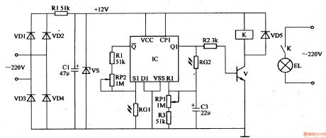
The 220v voltage will generate +12v voltage after reduction, rectification, stablization. The voltage will provide IC with working power. The other circuit will provide V2-V5 with working voltage.
IC's pin 14 will beconnected to +12V power. Every time S is connected, the positive pulse will be put on IC's pin 14, which will make IC have a count. When S is connected and disconnected intermittently, IC's Y0-Y8 will output high level which will make the thyristor connected. Then the lights will have 8 different illumination states. (View)
View full Circuit Diagram | Comments | Reading(617)
F117 Integrated Circuit Typical Application Circuit (2)
Published:2011/6/21 19:39:00 Author:Robert | Keyword: Integrated Circuit, Typical, Application

The F117 is a single-chip micro-computer integrated circuit for communication which is widely used in Fengling series full-standard caller-ID IP telephones.
The IP telephone control system typical application circuit composed of F117 integrated circuit is shown in the picture.
The picture shows the F117 integrated circuit's typical application circuit. (View)
View full Circuit Diagram | Comments | Reading(535)
Light-Operated Neon Light (2)
Published:2011/7/3 3:01:00 Author:Sue | Keyword: Light-Operated, Neon, Light
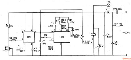
The 220v working voltage will provide IC1 with +8.4 working voltage after reduction, stablization, rectification and filtration.
In the daytime, RG will have a low resistance value because of light, IC1's pin 2 and pin 6 will have high level. Pin 3 will output low level. VT is disconnected. HL doesn't work.
When it is dark, RG will have a high resistance value because of lack of light. IC1's pin 2 and pin 6 will have low level. IC2 will begin to work and begin to count. Its pin 3 will output low level. V and VT are disconnected. When time is over, IC2's pin 3 will become high level. V and VT are connected. HL stops working. (View)
View full Circuit Diagram | Comments | Reading(612)
Increasing Input Impedance Circuit
Published:2011/6/21 19:41:00 Author:Robert | Keyword: Increasing, Input, Impedance

The picture shows the circuit which increases the input impedance by adding front amplifier stage.
Those amplifier circuit, which used in small current amplification or large signal internal resistance case, needs very high input impedance. Some could be more than 1x10¹²Ω. To increase the input impedance, the most direct way is to use the input stage composed of FET and add it in parallel before the amplifier. The circuit in the picture can make the VT2 static working point stable. R1, R2 and RP1 is used to get the balance of the output voltage of the front amplifier stage. (View)
View full Circuit Diagram | Comments | Reading(583)
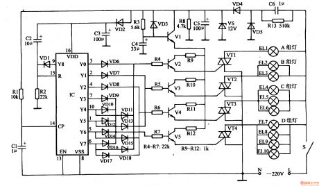
Light-Operated Neon Light (1)
Published:2011/7/3 2:55:00 Author:Sue | Keyword: Light-Operated, Neon, Light
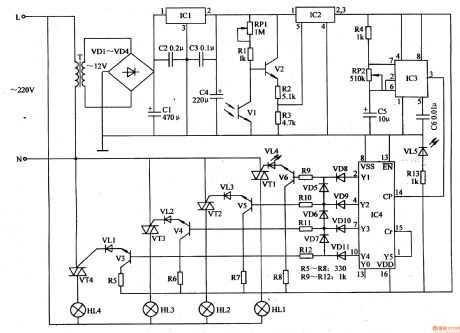
The 220v voltage will provide C4 with +12v working voltage after reduction, rectification, filtration and stablization.
In the daytime, V1 has a high resistance value because of the light, V2 is disconnected. IC2's inner switch is disconnected. IC3 and IC4 will have no working voltage. VT1-VT4 are disconnected. HL1-HL4 are not illuminated.
When it is dark, V1 has a low resistance value because of lack of light. V2 is connected. IC2's pin 5 has a high level. Its inner switch will be connected. Pin2 and pin 3 will output +12v voltage. IC3 and IC4 will begin to work. (View)
View full Circuit Diagram | Comments | Reading(589)
Light-Operated Streetlight (16)
Published:2011/7/1 6:38:00 Author:Sue | Keyword: Light-Operated, Streetlight
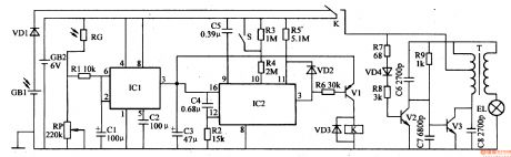
In the daytime, GB will be charged. RG will have a low resistance value which will make IC1's pin 2's and pin 6's voltages higher than 2Vcc/3. IC1's pin 3 will output low level. IC2 and V1 don't work. K is released and EL is not illuminated.
When it is dark, RG has a larger resistance value which will make IC1's pin 2's and pin 6's voltage become lower. When the voltage is lower than Vcc/3, IC1's inner circuit will be reversed. Its pin 3 will have high level. IC2 and V1 will begin to work. Then pin 3 will output low level which will makes V1 connected. K is connected. Then ELA will be illuminated. (View)
View full Circuit Diagram | Comments | Reading(474)
Typical application circuit of the reference voltage source
Published:2011/6/27 6:43:00 Author:Christina | Keyword: Typical application, reference voltage source
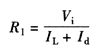
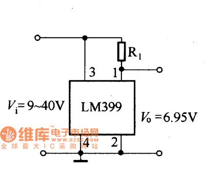
1.Typical application circuit of the LM399
The typical application circuit of the LM399 integrated reference voltage source is as shown in the figure. In actual use, you can use it as the voltage-regulator tube, so when you connect it with the power supply voltage, you need to add the appropriate current-limiting resistance R1. The resistance of R1 can be calculated from this formula:
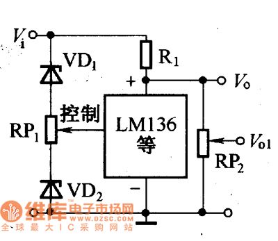
2.The typical application circuits of the LM136/236/336
The typical application circuits of the LM136/236/336 integrated reference voltage source are as shown in the figure.
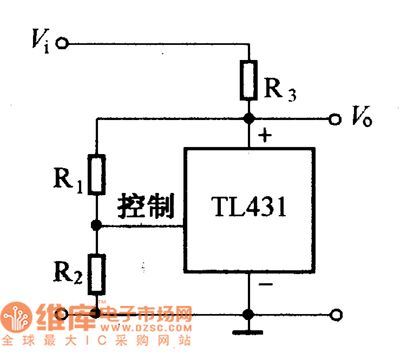
3.The typical application circuits of the TL431
The typical application circuits of the TM31 integrated reference voltage source are as shown in the figure.
The typical application circuit of LM399
The typical application circuit of LM136/236/336
The typical application circuit of TL431 (View)
View full Circuit Diagram | Comments | Reading(931)
Light-Operated Streetlight (15)
Published:2011/7/1 6:30:00 Author:Sue | Keyword: Light-Operated, Streetlight
The 220v voltage will provide the light-operated circuit with +12v working voltage after rectification, filtration and stablization.
In the daytime, RG1 and RG2 will have low resistance values. IC's S1 will output low level. R1 will output high level. Q1 will output low level. V is disconnected and K is released. EL is not illuminated.
When it is dark, RG1 and RG2 will have higher resistance values. IC's S1 will output high level. R1 will output low level. Q1 will output high level. V is connected and K is connected. EL will be illuminated. (View)
View full Circuit Diagram | Comments | Reading(422)
CW137 adjustable integrated voltage stabilizer typical application circuit
Published:2011/6/27 6:42:00 Author:Christina | Keyword: adjustable, integrated, voltage stabilizer, typical application

The CW137 adjustable integrated voltage stabilizer typical application circuit is as shown in the figure. The C1 is set to prevent the self-excitation of the circuit, VD1 is the protection diode. The C2 is connected between the adjust port and the grounding port of the voltage stabilizer, the function of it is to remove the ripple bypass of RP1 to improve the ripple suppression performance of the voltage stabilizer. After you add the C2 into the circuit, if the input port or output port shorts, the reverse peak current of Q will flow to the adjustment port to damage the reference voltage and the error amplifier.
CW137 adjustable integrated voltage stabilizer typical application circuit (View)
View full Circuit Diagram | Comments | Reading(686)
Static electricity medical health care device
Published:2011/7/1 1:14:00 Author:Nicole | Keyword: Static electricity, medical health care device
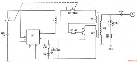
The static electricity medical health care device circuit is composed of DC boost circuit, high frequency oscillator and static electricity high voltage output circuit, it is shown in the figure 9-157.
The DC boost circuit is made of battery GB, power switch S, resistor R1, capacitor C, LED VL, boost integrated circuit IC and inductor L.
The high frequency oscillator circuit consists of transistor V, resistor R2, potentiometer RP and the winding W1, W2 of high voltage transformer T.
The static electricity high voltage output circuit is composed of T's winding W3, neon indicator light HL, resistor R3, rectifier diode VD and high voltage electrode A.
(View)
View full Circuit Diagram | Comments | Reading(1179)
Smoking telltale 2
Published:2011/6/27 1:20:00 Author:Nicole | Keyword: Smoking telltale
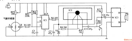
This smoking telltale circuit is composed of smog detector, monostable trigger, language generator and power amplifier circuit, it is shown in the figure 9-154.
The monostable trigger is made of time base integrated circuit IC1, resistor R2, capacitor C1 and potentiometer RP2.
The pronunciation generator circuit consists of language pronunciation integrated circuit IC2, resistors R3-R5, capacitor C2 and Zener diode VS.
The audio power amplifier circuit is composed of transistor V, boost power amplification module IC3, resistors R6, R7, capacitors C3, C4 and loudspeaker BL.
(View)
View full Circuit Diagram | Comments | Reading(511)
Smoking telltale 1
Published:2011/6/27 1:30:00 Author:Nicole | Keyword: Smoking telltale
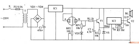
This smoking telltale circuit is composed of power supply, smog detector circuit and pronunciation circuit, it is shown in the figure 9-153.
The power supply is made of power supply transformer T, rectifier diodes VD1-VD4, filter capacitor C1 and three terminals integrated regulator IC1.
The smog detector circuit consists of gas sensitivity sensor, transistor V1 and other peripheral devices.
The pronunciation circuit is composed of pronunciation integrated circuit IC1(internal store the pronunciation Do not smoking pronunciation prompt), audio amplifier tube V2 and loudspeaker BL.
(View)
View full Circuit Diagram | Comments | Reading(517)
Elevator motor overspeed controller
Published:2011/7/1 1:30:00 Author:Nicole | Keyword: elevator, motor, overspeed controller
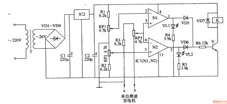
The elevator motor overspeed controller circuit is composed of power supply circuit, LED indication circuit and speed measurement control circuit, it is shown in the figure 8-66.
The power supply circuit is made of power transformer T, rectifier diodes VD1-VD4, filter capacitors C1, C2 and there terminals steady voltage integrated circuit IC2.
The LED indication circuit consists of LED VL1, VL2 and resistors R4, R5.
The speed measurement control circuit is composed of resistors R1-R6, potentiometers RP1, RP2, operation amplifier integrated circuit IC1(N1, N2), diodes VD5-VD7, transistor V and relay K.
(View)
View full Circuit Diagram | Comments | Reading(1969)
Transfusion warmer 2
Published:2011/6/27 1:53:00 Author:Nicole | Keyword: Transfusion warmer
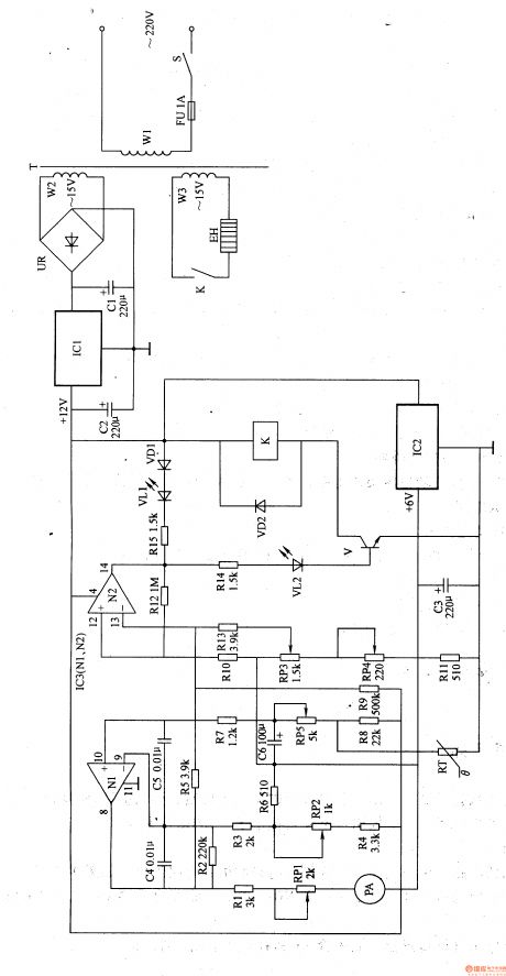
This transfusion warmer circuit is composed of power supply and temperature detector control circuit, it is shown in the figure 9-152.
The power supply circuit is made of power supply switch S, fuse FU, power transformer T, bridge rectifier UR, there terminals steady voltage integrated circuit IC1, IC2 and fliter capacitors C1-C3.
The temperature detector control circuit consists of thermal resistor RT, resistors R1-R5, potentiometers RP1-RP5, capacitors C4-C6, diodes VD1, VD2, LED VL1, VL2, transistor V, ammeter PA, relay K and operation amplifier integrated circuits IC3(N1, N2).
(View)
View full Circuit Diagram | Comments | Reading(510)
| Pages:1623/2234 At 2016211622162316241625162616271628162916301631163216331634163516361637163816391640Under 20 |
Circuit Categories
power supply circuit
Amplifier Circuit
Basic Circuit
LED and Light Circuit
Sensor Circuit
Signal Processing
Electrical Equipment Circuit
Control Circuit
Remote Control Circuit
A/D-D/A Converter Circuit
Audio Circuit
Measuring and Test Circuit
Communication Circuit
Computer-Related Circuit
555 Circuit
Automotive Circuit
Repairing Circuit