
Circuit Diagram
Index 1631
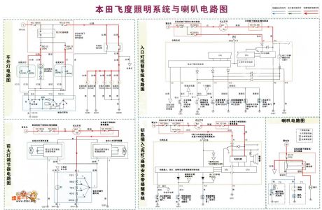
Honda Fit lighting system with speakers circuit
Published:2011/7/4 0:27:00 Author:John | Keyword: lighting system, speaker
View full Circuit Diagram | Comments | Reading(1200)
TV remote control 08 circuit
Published:2011/7/4 0:19:00 Author:John | Keyword: TV remote control

View full Circuit Diagram | Comments | Reading(632)
TV remote control 07 circuit
Published:2011/7/4 0:20:00 Author:John | Keyword: TV remote control

View full Circuit Diagram | Comments | Reading(683)
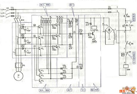
Compressor phase protection circuit
Published:2011/7/4 0:19:00 Author:John | Keyword: Compressor
View full Circuit Diagram | Comments | Reading(953)
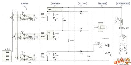
sound and light of resistance furnace alarming circuit
Published:2011/7/4 0:17:00 Author:John | Keyword: resistance furnace
View full Circuit Diagram | Comments | Reading(597)
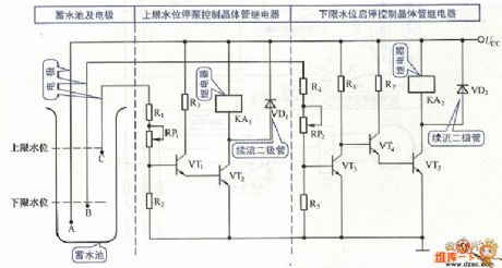
Pump starting-stoping control circuit
Published:2011/7/4 0:22:00 Author:John | Keyword: Pump
View full Circuit Diagram | Comments | Reading(467)
Circuit Diagram of Photoelectronic Pulse Omission Detection Composed of 556
Published:2011/7/2 1:03:00 Author:Vicky | Keyword: Photoelectronic Pulse Omission Detection
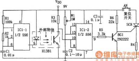
There is a several millimetric slit between the luminotron and photosensitive tube inside photoelectronic switch H13B1. When light-isolator object from outside is plugged into the slit, the photosensitive tube inside H13B1 presents high impedance because of the cutting-off of the beam of light. Then the IC1-2(1/2 556) sends out high level because that the pulse signal detection cannot receives reset signal, and it turns into a transient stability state. The correspondent transient stability time is td=1.1RwlC2 and the td can be changed by modulating W1. If the signal interrupting duration is longer than the transient stability time, IC1-2 resets, pin ③ sends out low level which stops BG1, SCR is conducted and the load RL is correspondently conducted. It will either cut down the power supply circuit or send out alarming signal. (View)
View full Circuit Diagram | Comments | Reading(660)
TV remote control 06 circuit
Published:2011/7/4 0:22:00 Author:John | Keyword: TV remote control

View full Circuit Diagram | Comments | Reading(595)
TV remote control 05 circuit
Published:2011/7/4 0:25:00 Author:John | Keyword: TV remote control

The resistance forresistors marked with * is optional within10k-100k, which is set aslarge as possible.
(View)
View full Circuit Diagram | Comments | Reading(653)
Polaris JD-11W electronic ballast circuit diagram
Published:2011/6/30 22:37:00 Author:Ecco | Keyword: Polaris , electronic ballast

View full Circuit Diagram | Comments | Reading(1801)
Precision regulated DC power supply circuit diagram made by TL431
Published:2011/7/1 2:16:00 Author:Ecco | Keyword: Precision , regulated , DC power supply

View full Circuit Diagram | Comments | Reading(6156)
Transistor switching circuit diagram
Published:2011/6/30 3:08:00 Author:Ecco | Keyword: Transistor, switching
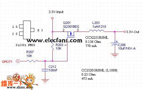
In the Figure: when GPIO end is low, the transistor turns on, then the pin 3 output is 3. 3V; when GPIO terminal is high, the transistor is off, the pin 3 output is 0V.
(View)
View full Circuit Diagram | Comments | Reading(684)
2.1 channel active speaker wiring diagram
Published:2011/6/30 3:06:00 Author:Ecco | Keyword: 2.1 channel , active , speaker, wiring

View full Circuit Diagram | Comments | Reading(3992)
LA4261 audio IC circuit diagram
Published:2011/6/28 2:41:00 Author:Ecco | Keyword: audio IC

View full Circuit Diagram | Comments | Reading(1466)
HA1388 audio IC circuit diagram
Published:2011/7/1 1:40:00 Author:Ecco | Keyword: audio IC

View full Circuit Diagram | Comments | Reading(1296)
The amplifier circuit diagram for measuring small current
Published:2011/7/1 1:51:00 Author:Ecco | Keyword: amplifier , measuring, small current

View full Circuit Diagram | Comments | Reading(625)
Dahua YZ-88-7W electronic ballast circuit diagram
Published:2011/7/1 1:52:00 Author:Ecco | Keyword: Dahua , electronic ballast

View full Circuit Diagram | Comments | Reading(1272)
Dark current negative feedback differential amplifier circuit diagram
Published:2011/7/1 1:56:00 Author:Ecco | Keyword: Dark current , negative feedback , differential amplifier

View full Circuit Diagram | Comments | Reading(1723)
9 W (5 W) electronic ballast circuit diagram
Published:2011/7/1 1:57:00 Author:Ecco | Keyword: 9 W , 5 W , electronic ballast

View full Circuit Diagram | Comments | Reading(2470)
Rong Gan 13 electronic ballast circuit diagram
Published:2011/7/1 1:39:00 Author:Ecco | Keyword: Rong Gan 13 lectronic ballast

View full Circuit Diagram | Comments | Reading(1439)
| Pages:1631/2234 At 2016211622162316241625162616271628162916301631163216331634163516361637163816391640Under 20 |
Circuit Categories
power supply circuit
Amplifier Circuit
Basic Circuit
LED and Light Circuit
Sensor Circuit
Signal Processing
Electrical Equipment Circuit
Control Circuit
Remote Control Circuit
A/D-D/A Converter Circuit
Audio Circuit
Measuring and Test Circuit
Communication Circuit
Computer-Related Circuit
555 Circuit
Automotive Circuit
Repairing Circuit