
Circuit Diagram
Index 1637
TA8152AFN TV/FM radio integrated circuit
Published:2011/7/1 1:04:00 Author:chopper | Keyword: TV/FM, radio, integrated circuit
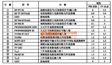
TA8152AFN is a FN/FM radio integrated circuit produced by Company TOSHIBA,and it is applied to the sound system,computer sound system.TA8152AFN adopts dual inline 16 pinned package.And its function and data of pins of integrated circuit are shown as chart 1.
(View)
View full Circuit Diagram | Comments | Reading(647)
EB-03 Communication Single-Chip Micro-Computer Integrated Circuit
Published:2011/7/3 9:40:00 Author:Robert | Keyword: Communication, Single-Chip, Micro-Computer, Integrated


The EB-03 is a communication single-chip micro-computer IC which is widely used in Henghui series caller ID telephones.
1.Its functional features.
The EB-03 IC has internal clock oscillation circuit, key-bit pulse generating circuit, key-bit command coding circuit, dual-tone multi-frequency circuit, hands-free system caller ID control circuit, caller-inquiry circuit, hands-free trigger, serial data interface (providing displaying and storing data), mechanical lock and automatic recovering dialing circuit and other functional circuit.
2.Its pin's function and data
The EB-03 IC uses 28-pin dual-row package and its pin's function and data is listed in table 1.
The table 1 shows the EB-03 IC's pin's function and data.
3.Typical application circuit
The caller ID display control system typical application circuit composed of EB-03 IC is shown in picture 1.
The picture 1 shows the EB-03 IC's typical application circuit. (View)
View full Circuit Diagram | Comments | Reading(571)
low-noise preamplifier circuit of OPA37
Published:2011/7/1 0:53:00 Author:chopper | Keyword: low-noise, preamplifier circuit

The picture shows the low-noise preamplifier of OPA37. The input signal is applied to OPA37 inverting input (pin 3). RL,CL in the circuit are the load impedances of the electromagnetic pick-up,and their resistances and capacities follow the characteristics of the pick-up(Generally they are based on the recommended parameters ). The all resistors should adopt metal film resistors (1% accuracy), and their capacitors should use organic film capacitors. When the input signal is 1kHz, its gain will be about 100 times. (View)
View full Circuit Diagram | Comments | Reading(969)
Darlington Type Phototransistor Optical Control Switch Application Circuit
Published:2011/7/3 6:42:00 Author:Robert | Keyword: Darlington, Phototransistor, Optical Control, Switch, Application

The picture shows the darlington type phototransistor optical control switch application circuit.
Because of using the darlington type phototransistor as the sensor element, it is sensitive to weak light. It is adequate for the detection of reflected light signal. (View)
View full Circuit Diagram | Comments | Reading(1515)
3ACM And 3BCM Type Magnetic Transistor Shape Circuit
Published:2011/7/3 9:10:00 Author:Robert | Keyword: Magnetic, Transistor, Shape
The picture shows the 3ACM and 3BCM type magnetic transistor shape circuit. (View)
View full Circuit Diagram | Comments | Reading(1115)
ultrasonic remote switch (C033) circuit
Published:2011/6/30 1:15:00 Author:chopper | Keyword: ultrasonic, remote switch
View full Circuit Diagram | Comments | Reading(394)
The self-made temporary power supply circuit
Published:2011/7/1 22:39:00 Author:Borg | Keyword: self-made, temporary power supply

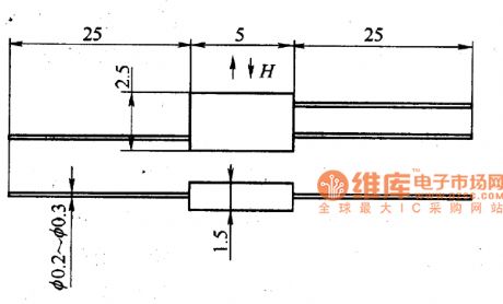
1. The circuit principle The transistor V, the coils of N1 and N2 of transformer T and capacitor C compose the transformer coupling LC oscillator circuit. The potentiometer RP and resistor R provides with a bias current of the oscillator. 2. Elements selection V is adopted with 3DD59A, R is the 1/4W ordinary resistor, C is 0.22μF/50V, the transformer is self-made, N1 and N2 are the 0.9mm covered wire, the N3 coil is the 0.67mm covered wire, the coil frame can be made by the hard paper board of 1mm, the magnet would better be the ferrite of U or loop shape, if not, it can be replaced by the silicon sheet of E or F shape.
(View)
View full Circuit Diagram | Comments | Reading(736)
the circuit of the temperature and humidity automatic controller (1)
Published:2011/6/21 7:04:00 Author:Ariel Wang | Keyword: temperature , humidity, automatic controller
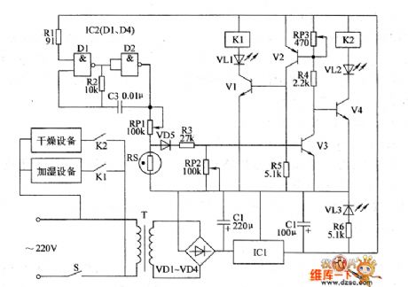
When the value of temperature and humidity in monitor room is beyond the set value,the voltage of IC2's pin-6 is lower than the voltage of pin-5. The in-circuit of IC2 overturns.Pin-3 outputs high level.K is pulled over.The normally open contacts K1-1 and Kl-2 are connected.The discharge fan and the ventilator get to work until the value of temperature and humidity in monitor room is within the set value.RP1 is used to set the value of temperature in monitor room.RP2 is used to set the value of humidity in monitor room.When you adjust it,you should put S at the position of adjusting .Then you should adjust the resistence of RP1 and RP2.When you use it,you should put S at the position of automatic .
(View)
View full Circuit Diagram | Comments | Reading(454)
the circuit of the multifunctional protector for electric motor(3)
Published:2011/6/22 7:38:00 Author:Ariel Wang | Keyword: multifunctional protector, electric motor(
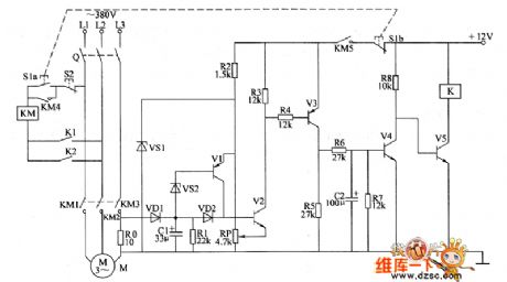
When 51 gets through,V5 is saturated to conduct.K is pulled in.The normally open contacts K1 and Φ are connected.KM acts.Then the electric motor M works.At the same time,the current detect and control circuit is conducted to work.When the electric motor is working,the voltage of R0 is low.VI~V4 are stopped.V5 stays conducted.When the electric motor is overload or the working voltage is low,the voltage of R0 increases.V2~V4 are conducted.V5 is stopped.K is released.The normally open contact K1 is disconnected.KM is power down.So KM is released.The electric motor M is power down.So it is stopped.
(View)
View full Circuit Diagram | Comments | Reading(416)
The PWM realization circuit of the analog circuit
Published:2011/7/1 23:13:00 Author:Borg | Keyword: PWM, realization circuit, analog circuit
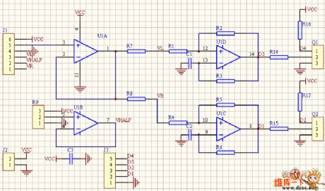
In the figure is the PWM generating circuit of the two chassises drive motor controlled by the linear circuit of game controller or the model airplane racker. J1 is the outlet of the racker, 123 and 456 are the potentiometer of the x and y dimension. U1B provide with the half power supply voltage, U1A is the voltage follower. The x and y become the voltage signal which controls the rotating speed of the left and right wheel after being compounded. While in use, we make L=(x+1)y/(x+1.4), R=(x-1)y/(x-0.6), and the effect proves to be good after the practice.
(View)
View full Circuit Diagram | Comments | Reading(556)
The grid voltage fault protection indicating circuit
Published:2011/7/1 23:41:00 Author:Borg | Keyword: grid voltage, fault protection
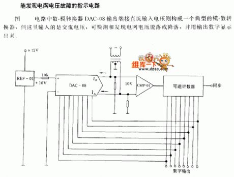
The indicating circuit of grid voltage fault discovery In the figure, the output terminal of the D/A converter DAC-08 is directly connected with the DC input voltage, which composes a typical A/D converter, but the input is an AC voltage here, which can detect and find out the grid voltage peeling or dropping, and the output digit can be displayed.
(View)
View full Circuit Diagram | Comments | Reading(849)
The rolling code encoding wireless emitting circuit(HSC360/TDA5100)
Published:2011/7/1 21:30:00 Author:Borg | Keyword: rolling code, wireless emitting circuit
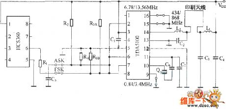
Figure:The rolling code encoding wireless emitting circuit(HSC360/TDA5100)TDA5100 is a ultra-high frequency wireless emitting circuit produced by Seimens, whose internal structure is complex, function is full, sensibility is high, output signal amplitude is high, external elements are few and price is low, it is a excellent emitting circuit. (View)
View full Circuit Diagram | Comments | Reading(1247)
the circuit of the multifunctional protector for electric motor(2)
Published:2011/6/23 6:12:00 Author:Ariel Wang | Keyword: multifunctional protector , electric motor
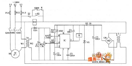
When there is phase lacking in L1 and L2,the current of L3 will increase rapidly(about 1.73 times normal current).The induced voltage of TA's winding on W2 is increased.The voltage of IC's pin-6 is higher than 2Vcc/3.The high level of pin-3 becomes low level.K is pulled in.The normally closed contacts are disconnected.KM is released as it is power down.The working voltage of electric motor M is cut off by the normally open contacts KM1~KM4.If there's phase lacking in L3,there will be no the induced voltage from TA.It is similar as the low level goes to pin-4 of IC .Pin-3 of IC outputs low level.K is pulled in.KM is released.Electric motor M stops working.
(View)
View full Circuit Diagram | Comments | Reading(362)
The over voltage/current protection circuit
Published:2011/7/2 2:49:00 Author:Borg | Keyword: over voltage/current, protection

When the voltage of the power supply is too high or the load attracts too much current, the circuit in the figure can break down the load and offer fault indication.
When it is normally working, both Tr1 and Tr2 are blocked, 555 is reset, the discharging transistor in 555 is conducting, it attracts power from Tr3 basic pole, which saturates Tr3, so the 5~12V power supply is sent to the main load directly. When the load gets too much current, the voltage drop on Rsc increases, which makes Tr1 conducting, so 555 is triggered and the discharge transistor in it is blocked, then Tr3 is blocked with it, the power supply and load are separated, at the moment, 555 is in single steady state. (View)
View full Circuit Diagram | Comments | Reading(913)
The infrared burglarproof alarm circuit
Published:2011/7/1 22:51:00 Author:Borg | Keyword: infrared, burglarproof alarm
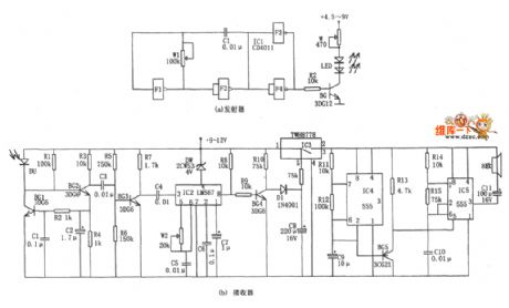
In the figure is the infrared burglarproof alarm circuit. The alarm includes the infrared pulse emitter and receiver, the decoder and alarm stereo circuit, and the emitter and receiver are installed on the same metal base. The emitter is a multi-resonance oscillator composed of 4 NAND CD4011 with two input terminals, whose oscillating frequency is decided by W1 and C1, the frequency corresponding to the figured parameters is about 1~15kHzm, the oscillating signal is turned into the infrared pulse signal after it is driven by BG. The infrared receiver and decoder includes the infrared light-electricity converter and so on.
(View)
View full Circuit Diagram | Comments | Reading(626)
the circuit of the temperature controller(13)
Published:2011/6/25 20:48:00 Author:Ariel Wang | Keyword: temperature controller
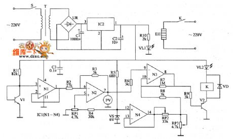
When then environment temperature detected by V1 is lower than the temperature set by RP3,N3 outputs low level(about 0.65V).V2 is saturated to conduct.K is conducted to pull in.VL2 is lighted.The electric heater is conducted to work.The environment temperature goes up slowly.When the temperature rises to the set temperature,N3 outputs low level(about 7.7V).V2 is stopped.K is released.VL2 dies out.The electric heater EH is power off.So it stopes heating.Soon after,the environment temperature goes down slowly,when the temperature goes down to the set temperature.K is pulled in.EH is conducted to heat.It goes on and on.So the temperature in the controlled place is around the set temperature.
(View)
View full Circuit Diagram | Comments | Reading(429)
The infrared sound/light alarm circuit
Published:2011/7/1 23:23:00 Author:Borg | Keyword: infrared, sound/light alarm
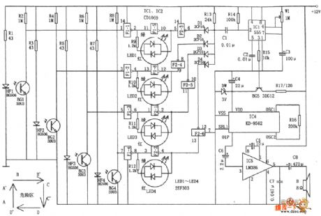
In the figure is the infrared sound/light alarm circuit.The circuit consists of the AND gate circuit, single steady time delay circuit, 4 lines of infrared emitter and the reception circuit, trigger and 2-color light circuit, stereo alarm circuit and so on. The alarm is used in alarm area, and the range is shown in the figure. The infrared LED HF1~HF4 and the coupling pipes BG1~BG4(3DU31) compose 4 pairs of emitting and receiving warning lines.If someone is passing the warning line, the infrared ray is blocked, so the corresponding coupling pipe is blocked and the NAND inputting a high LEV.
(View)
View full Circuit Diagram | Comments | Reading(1175)
the circuit of the animal littering announcer (1)
Published:2011/6/28 6:06:00 Author:Ariel Wang | Keyword: animal baby, announcer
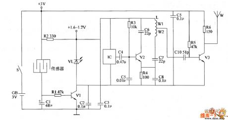
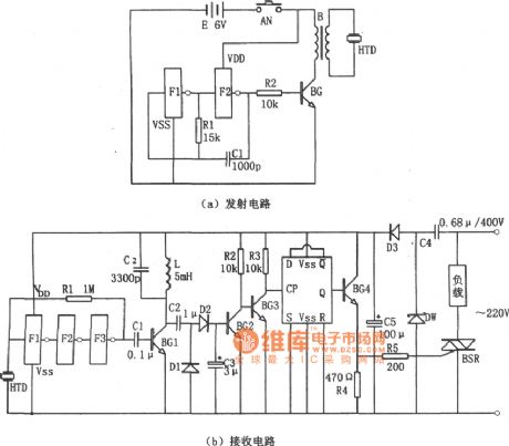
When the animals have babies,the resistence between two crossed electrodes of the comb-like sensor become small.V1 is saturated to conduct.VL is lighted.The +3V voltage is current limited by R2.It is connected with VL and V2 in series.And it is regulated by them.Then it provides IC and the high frequency oscillator (consists of R3,R3,C4~C8,L1 and V2) 1.6~1.7V DC working voltage.IC outputs the acoustics signal.It is modulated by the high frequency oscillator.And it is power amplified by V2.Then it is emitted by antennas W to the sky.The feeder can recieve the alarm signal of having animal babies by FM in a distance.
(View)
View full Circuit Diagram | Comments | Reading(398)
the circuit of the chickling hatching announcer(3)
Published:2011/6/28 5:59:00 Author:Ariel Wang | Keyword: chickling, hatching, announcer
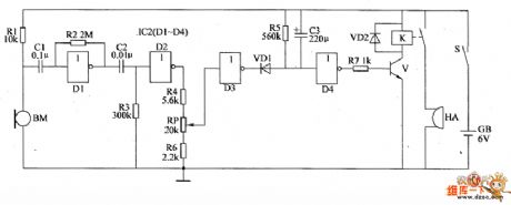
When the mains switch gets through,the whole control circuit is at the state of waiting.The not gate circuit D4 outputs low level.The transistor V is stopped.The relay K is released.HA doesn't give a sound.When there are baby chicken ,BM will convert the sound of the chickling to the electric signal.The electric signal is amplified by not gate D1,reversal processed by D2.Then it outputs high level.The output end of not gate D3 outputs low level.The LED VD1 is conducted.The output end of not gate D4 outputs high level.The transistor V is saturated to conduct.The relay K is conducted to pull in.The normally open contacts are connected.HA gives out alarm sound. (View)
View full Circuit Diagram | Comments | Reading(440)
the circuit of the chickling hatching announcer(1)
Published:2011/6/28 7:19:00 Author:Ariel Wang | Keyword: chickling hatching , announcer
The 220V AC voltage is current limited by R1,commutated by VD,regulated by VS and filtered by C1.It provides +12V working voltage for the audio amplifier circuit.When there is no chickling hatching from the eggs in the incubator.BM can't detect the sound signal.V2 and VT aren't conducted.HA doesn't give a sound.VL and HL aren't lighted.When there is chickling hatching out from the eggs,BM will convert the sound of the chickling into the electric signal.The signal is amplified by V1.V2 is conducted.VL is lighted.VT is triggered to conduct.HA is conducted to alarm.HL is lighted.You can change the capacitance to adjust the sensitivity of the alarm circuit.
(View)
View full Circuit Diagram | Comments | Reading(335)
| Pages:1637/2234 At 2016211622162316241625162616271628162916301631163216331634163516361637163816391640Under 20 |
Circuit Categories
power supply circuit
Amplifier Circuit
Basic Circuit
LED and Light Circuit
Sensor Circuit
Signal Processing
Electrical Equipment Circuit
Control Circuit
Remote Control Circuit
A/D-D/A Converter Circuit
Audio Circuit
Measuring and Test Circuit
Communication Circuit
Computer-Related Circuit
555 Circuit
Automotive Circuit
Repairing Circuit