Control Circuit
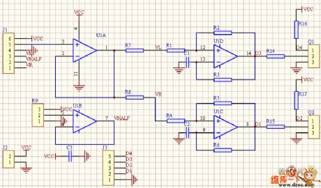
The PWM realization circuit of the analog circuit
Published:2011/7/1 23:13:00 Author:Borg | Keyword: PWM, realization circuit, analog circuit | From:SeekIC

In the figure is the PWM generating circuit of the two chassises drive motor controlled by the linear circuit of game controller or the model airplane racker. J1 is the outlet of the racker, 123 and 456 are the potentiometer of the x and y dimension. U1B provide with the half power supply voltage, U1A is the voltage follower. The x and y become the voltage signal which controls the rotating speed of the left and right wheel after being compounded. While in use, we make L=(x+1)y/(x+1.4), R=(x-1)y/(x-0.6), and the effect proves to be good after the practice.
Reprinted Url Of This Article:
http://www.seekic.com/circuit_diagram/Control_Circuit/The_PWM_realization_circuit_of_the_analog_circuit.html
Print this Page | Comments | Reading(3)

Article Categories
power supply circuit
Amplifier Circuit
Basic Circuit
LED and Light Circuit
Sensor Circuit
Signal Processing
Electrical Equipment Circuit
Control Circuit
Remote Control Circuit
A/D-D/A Converter Circuit
Audio Circuit
Measuring and Test Circuit
Communication Circuit
Computer-Related Circuit
555 Circuit
Automotive Circuit
Repairing Circuit
Code: