
Circuit Diagram
Index 1626
S-8054AKR application circuit diagram
Published:2011/6/30 13:33:00 Author:Sophia | Keyword: S-8054AKR, application circuit

(View)
View full Circuit Diagram | Comments | Reading(540)
EL display driving circuit composed of NE555
Published:2011/7/3 19:37:00 Author:Lucas | Keyword: EL display , driving circuit
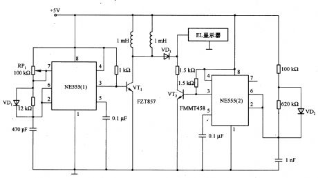
Light-emitting EL display has the advantages of long life (about l00OOh), light uniformity and low loss, and it is equivalent to the LCD for low-light-emitting display, which includs mobile phone, watch and automated meter display. The conventional EL drive circuit uses flyback converter to produce enough high-voltage EL light, if taking into account the cost of the converter and the space, this solution is too expensive. The advantage of EL display driver is that it is composed of low-loss NE555 and several switching transistors.
(View)
View full Circuit Diagram | Comments | Reading(2192)
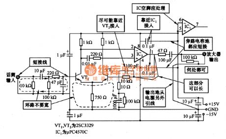
Practical technique circuit of artificial circuit layout and design
Published:2011/6/30 13:25:00 Author:Sophia | Keyword: Practical technique, Artificial circuit layout and design
(View)
View full Circuit Diagram | Comments | Reading(562)
Water level control circuit
Published:2011/7/2 21:28:00 Author:Lucas | Keyword: Water level , control
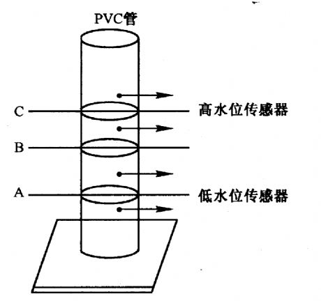

Figure 2-23 (a) shows the sensor. There are two pairs of wires being installed in the corresponding water level A and C inside of the PVC pipe, only when the water level rises more than A, B and C, the pump will stop running. When the water level drops below the C and B, pump will maintain working. Only when the water level is lower than A, the pump is switched on to run. Figure 2-23 (b) shows the pump motor control circuit. In the circuit, Al-A4 use 5V single supplied TLC2274 op amp. Among them, Al and A2 form the comparator to control D flip-flop 7474 and add the reference voltage with about 4V at inverting input end of A3 and A4.
(View)
View full Circuit Diagram | Comments | Reading(1683)
Mosfet Power Amplifier Circuit
Published:2011/7/1 3:35:00 Author:Joyce | Keyword: Mosfet, Power Amplifier

As shown in the figure is a power amplifier circuit consisting of MOSFET tube.The second differential motion in the circuit uses medium power MOSFET 2SJ77 , and the current mirror circuit uses 2SK214. The working current is 6 mA. Since the voltage of power supply is high( ±50V), the transistor will get hot, so a small radiator should be connected. (View)
View full Circuit Diagram | Comments | Reading(6120)
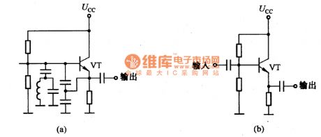
Oscillation circuit of the emitter follower
Published:2011/6/30 13:01:00 Author:Sophia | Keyword: Emitter follower, Oscillation
(View)
View full Circuit Diagram | Comments | Reading(983)
100W Mosfet Power Amplifier Circuit
Published:2011/7/1 3:12:00 Author:Joyce | Keyword: Mosfet, power amplifier

MOSFET power amplifier circuit is mainly used in high-power AV circuits. As shown in the figure is the 100 W MOSFET power amplifier circuit. The input stage of the circuit uses JEFT input op-amp TL071, which has a high input impedance and conversion rate. VT1 and VT3 are complementary constant current source loads of op-amp TL071. VT4 and VT5 compose a typical driver stage, and it has a good linearity and fast response. The output stage VT6 and VT7 use MOSFET tube. They have beautiful timbre and the amplification factor is 5. C1 uses metallized polypropylene capacitor to avoid distortion. (View)
View full Circuit Diagram | Comments | Reading(10856)
Lighting and signal basic circuit diagram of Beijing "City Cat People" 2020SG puddle jumper
Published:2011/6/30 12:12:00 Author:Sophia | Keyword: Beijing "City Cat People" 2020SG puddle jumper, Lighting, signal basic circuit
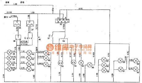
1. integrated switches Integrated switch on the steering column below the steering wheel, its features are: headlight dimmer, overtaking, turning, hazard warning switch gears and horn buttons, and it can rely on the steering wheel back body to automatically turn off the lights. 2. the fog lamp switch Left and right side of front bumper of BJ20205G has two fog lamps 29, 30, to open the fog lamp switch 31 can open the fog lights. 3. lighting switch Light switch 5O belongs to the JKlO1 type, there are three positions, namely close, l block, D block. (1) Ⅰ gear: it used to connect to front signal light 60, 61, tail lights 62 and 63, instrument lamp 57,58 and 59, license plate lights 56. (2) Ⅱ gear: In addition to accessing a variety of lights connecting to I blocking, it connects the headlamps 53, 54. simmer switch 52 chooses the distance light. Overtaking signal is sent by the switch 51. (View)
View full Circuit Diagram | Comments | Reading(1028)
The follower circuit diagram of steady operation
Published:2011/6/30 10:45:00 Author:Sophia | Keyword: The follower, steady operation

(View)
View full Circuit Diagram | Comments | Reading(508)
The simple fluorescent lamp driver circuit
Published:2011/7/2 20:57:00 Author:Lucas | Keyword: simple, fluorescent lamp, driver circuit
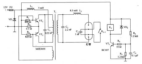
It is a self-excited push-pull converter which is conmposed of transformer and transistor. In the circuit, the transistor VT3, relay Kl, resistor R6 and capacitor C4 form the preheat circuit of fluorescent tube, and warm-up time is about 40Oms. When the relay Kl releases, then C3 is connected to the two ends of tube, it makes a certain voltage and current wave shape and increases the lamp power factor. Diode VDl and fuse FU are used to prevent reverse polarity voltage. Circuit switching frequency is about 25kHz, and its conversion efficiency is 75%.
(View)
View full Circuit Diagram | Comments | Reading(2153)
Pulse automatic charger 1
Published:2011/6/19 6:28:00 Author:Crystal Liu | Keyword: Pulse , automatic charger

Automatic pulse charger circuit is simple, low cost, safe and fast charging.Circuit characteristics are as follows:① Pulsed current charging the battery or dry cell, to overcome the battery memory effect ;② Charging current controled by limiting resistor R5 from the adjustment, usually can be transferred to 500mA current; ③The circuit can detects the charging voltage,when the battery voltage is close to the rated voltage,charging rate gradually slowed down,maintained at the end of the battery voltage on the dynamic; ④LED does not light a long time, to indicate charge complete.
(View)
View full Circuit Diagram | Comments | Reading(644)
The control circuit of two-phase servo motor
Published:2011/7/2 21:41:00 Author:Lucas | Keyword: control circuit , two-phase , servo motor

Two-phase servo motor has the field winding and control winding, when the phase difference is 90 °, it generates the rotation torque. The potentiometer connected to the motor shaft will get the voltage difference between the corresponding voltage and target value detected by potentiometer, and voltage difference is used as the error voltage, which is used as the input voltage of servo amplifier to control motor be consistent with the target value. And VTl and its associated components form the phase shift circuit, and MCl709 is the single-end output preamplifier of single power supply, and VT2-VT5 form the B complementary output circuit.
(View)
View full Circuit Diagram | Comments | Reading(5119)
High voltage follower circuit
Published:2011/7/4 19:21:00 Author:Lucas | Keyword: High voltage, follower
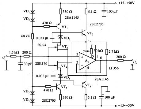
In the circuit, source follower circuit is composed of the VT3 and VT4, and Al is the voltage follower circuit, and the VT2 and VT6 connected to pin 7 and pin 4 of A1 form emitter follower circuit. The potential of pin 7 and pin 4 is the shifting of input signal voltage level, and therefore, the input signal is large, the voltage of output end and each power supply end keep constant with about 5V. As Al chip current signal flowing phase compensation capacitor is greatly improved, then the switching rate is increased and high-frequency distortion is greatly reduced.
(View)
View full Circuit Diagram | Comments | Reading(1481)
the circuit of the animal baby announcer (2)
Published:2011/6/27 23:36:00 Author:Ariel Wang | Keyword: animal baby , announcer
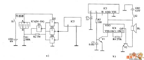
In normal times,the resistence between the sensor's electrode A and B is large.The input end of not gate D1 outputs low level.The output end outputs high level.The output ends of not gate D2~D4 output low level.IC2 stops working.The wireless receiving alarm circiut can't receive wireless alarm signal.The loudspeaker BL can't give a sound.When animals have babies,the resistence between the sensor's electrode A and B is small.The not gate outputs low level.The not gate D2~D4 output high level.IC2 is conducted to work.It emits wireless alarm signal to the sky.When IC3 recieves the wireless signal from IC2,the L end outputs high level,V1 is saturated to conduct.IC4 is conducted to work.The O/P end outputs acoustics signal.It is amplified by V2.The driver BL gives out alarm sound. (View)
View full Circuit Diagram | Comments | Reading(451)
The wiring diagram of DC meter
Published:2011/6/26 21:10:00 Author:Ecco | Keyword: wiring diagram , DC meter
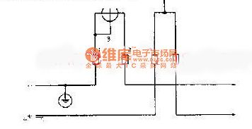
The DC circuit is generally tested by DC power meter. The common DC meter wiring method is shown as the chart. It has a voltage coil and a set of current coil, which are respectively connected in the tested circuit.
(View)
View full Circuit Diagram | Comments | Reading(519)
Op amp circuit diagram
Published:2011/6/24 2:43:00 Author:Ecco | Keyword: Op amp

There are two basic types of amplifier circuits: noninverting amplifier and the inverting amplifier. Their AC-coupled version is shown in Fig. For AC circuits, reverse means that the phase angle is moved in 180 degrees. This circuit uses a coupling capacitor-Cin. Cin is used to prevent circuit DC amplification, so the circuit will only produce amplification oon AC. In the DC circuit, Cin is omitted, then it must be calculated on the DC amplification. In the high-frequency circuits, it is very important to violate the op amp's bandwidth limitations or not.
(View)
View full Circuit Diagram | Comments | Reading(916)
the circuit of the chickling hatching announcer(2)
Published:2011/6/28 6:59:00 Author:Ariel Wang | Keyword: chickling hatching, announcer
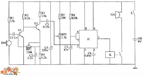
BM is as the audio sensor .It used to detect if there is any chickling hatching from the eggs.When the sound signal is not detected by BM.The mono-stable delay circuit is at the steady state.The pin-3 of IC outputs low level.K is released.The buzzer HA doesn't give a sound.When there is any chickling hatching from the eggs in the incubator.BM will convert the detected sound of the chickling into the electric signal.The signal is amplified by V1 and V2.Then it generates the triggering signal.The mono-stable trigger circuit is triggered to turn over.It turns to transient stability from steady state.The pin-3 of IC outputs high level from low level.K is conducted to pull in.The normally open contacts are connected.The buzzer HA gives out alarm sound.It informs the worker there are chicklings hatching from the eggs. (View)
View full Circuit Diagram | Comments | Reading(462)
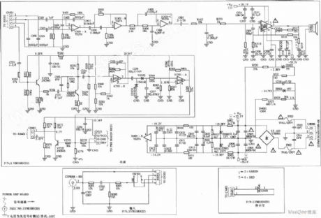
Philips Source Super Bass Loudspeaker Enclosure Power Amplifier Circuit
Published:2011/7/1 18:35:00 Author:Michel | Keyword: Philips, Source, Loudspeaker Enclosure, Power Amplifier, Circuit
View full Circuit Diagram | Comments | Reading(3323)
NJM2048 switching regulator control circuit (positive output)
Published:2011/6/30 20:47:00 Author:Lucas | Keyword: switching , regulator , control circuit , positive output

NJM2048 switching regulator control circuit (positive output), main features and pin of DC-DC circuit and power monitor
NJM2048 switching regulator control circuit (dual output)
It is the dual-output switching regulator control circuit; it is composed of the oscillator, voltage reference, comparator, protection circuit; it has 8.6V and 4.8V series of internal tracking , 4.8V series can be fine-tuning; maximum supply voltage is 20V; dual-row DIP package power is 700mW, micro-encapsulation is 300mV; Operating temperature is -20 ~ +75 ℃; it includes 5V reference voltage and soft-start function.
(View)
View full Circuit Diagram | Comments | Reading(725)
the circuit of the automatic anti-frosting controller for crops(1)
Published:2011/6/29 0:03:00 Author:Ariel Wang | Keyword: automatic, anti-frosting , controller, crops
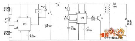
When the atmospheric temperature is higher than +1℃,the pin-2 of IC1 outputs the voltage lower than 3V.K is released.The high voltage ignition circuit stops working.When the temperature goes down an the condition of frost is formed,the resistence of RT is increased.The voltage of IC1's pin-6 is higher than 6V.The pin-3 outputs high level.K is conducted to pull in.The normally open contacts are connected.The high voltage ignition is conducted to work.It generates near 10000V DC voltage between electrodes of A and B.It lights the gunpowder and gasoline.The smoking material is infamed.
(View)
View full Circuit Diagram | Comments | Reading(453)
| Pages:1626/2234 At 2016211622162316241625162616271628162916301631163216331634163516361637163816391640Under 20 |
Circuit Categories
power supply circuit
Amplifier Circuit
Basic Circuit
LED and Light Circuit
Sensor Circuit
Signal Processing
Electrical Equipment Circuit
Control Circuit
Remote Control Circuit
A/D-D/A Converter Circuit
Audio Circuit
Measuring and Test Circuit
Communication Circuit
Computer-Related Circuit
555 Circuit
Automotive Circuit
Repairing Circuit