Automotive Circuit
the circuit of the animal baby announcer (2)
Published:2011/6/27 23:36:00 Author:Ariel Wang | Keyword: animal baby , announcer | From:SeekIC

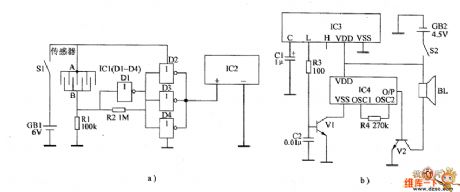
In normal times,the resistence between the sensor's electrode A and B is large.The input end of not gate D1 outputs low level.The output end outputs high level.The output ends of not gate D2~D4 output low level.IC2 stops working.The wireless receiving alarm circiut can't receive wireless alarm signal.The loudspeaker BL can't give a sound.When animals have babies,the resistence between the sensor's electrode A and B is small.The not gate outputs low level.The not gate D2~D4 output high level.IC2 is conducted to work.It emits wireless alarm signal to the sky.When IC3 recieves the wireless signal from IC2,the L end outputs high level,V1 is saturated to conduct.IC4 is conducted to work.The O/P end outputs acoustics signal.It is amplified by V2.The driver BL gives out alarm sound.
Reprinted Url Of This Article:
http://www.seekic.com/circuit_diagram/Automotive_Circuit/the_circuit_of_the_animal_baby_announcer_2.html
Print this Page | Comments | Reading(3)

Article Categories
power supply circuit
Amplifier Circuit
Basic Circuit
LED and Light Circuit
Sensor Circuit
Signal Processing
Electrical Equipment Circuit
Control Circuit
Remote Control Circuit
A/D-D/A Converter Circuit
Audio Circuit
Measuring and Test Circuit
Communication Circuit
Computer-Related Circuit
555 Circuit
Automotive Circuit
Repairing Circuit
Code: