Circuit Diagram
Index 1630
100MHz quartz crystal oscillator circuit
Published:2011/7/4 6:12:00 Author:Christina | Keyword: 100MHz, quartz crystal, oscillator
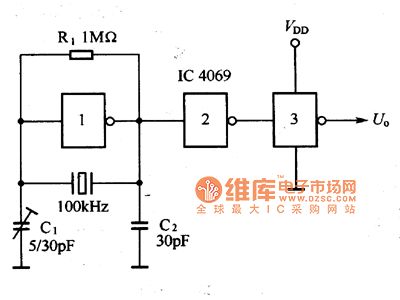
The high precision frequency oscillator circuit which is composed of the 100kHz quartz crystal resonator and the phase inverter is as shown in the figure 1, the phase inverter 2 and phase inverter 3 are the shaping circuit.
Figure 1 The 100kHz quartz crystal oscillator circuit
(View)
View full Circuit Diagram | Comments | Reading(3026)
1MHz quartz crystal oscillator circuit
Published:2011/7/4 6:08:00 Author:Christina | Keyword: 1MHz, quartz crystal, oscillator

The oscillator circuit which is composed of the 1MHz quartz crystal resonator and the NAND gate is as shown in the figure, the NAND gate 3 is the output buffer stage. This circuit can be used to calibrate the standard frequency.
Figure 1 The 1MHz quartz crystal oscillator circuit
(View)
View full Circuit Diagram | Comments | Reading(2483)
The low-speed single steady circuit
Published:2011/7/4 4:32:00 Author:Seven | Keyword: low-speed, single steady circuit
View full Circuit Diagram | Comments | Reading(443)
The low-frequency astable circuit
Published:2011/7/4 4:33:00 Author:Seven | Keyword: low-frequency, astable circuit
View full Circuit Diagram | Comments | Reading(583)
The key switch circuit
Published:2011/7/4 4:34:00 Author:Seven | Keyword: key switch
View full Circuit Diagram | Comments | Reading(531)
The key waking circuit
Published:2011/7/4 4:30:00 Author:Seven | Keyword: key waking
View full Circuit Diagram | Comments | Reading(744)
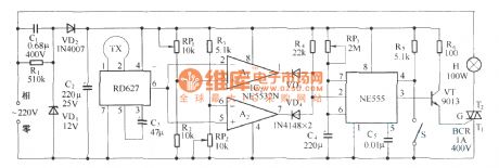
The balcony burglarproof lamp
Published:2011/7/4 5:56:00 Author:Borg | Keyword: balcony burglarproof lamp
View full Circuit Diagram | Comments | Reading(454)
The cultural relic security alarm circuit of ND-2
Published:2011/7/4 19:42:00 Author:Borg | Keyword: cultural relic, security alarm
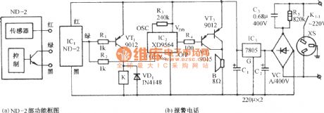
The circuit is shown in Figure (b), which consists of the vibrating sensor, relay control circuit, alarm sound generating circuit, audio power amplifier circuit and AC step-down rectifier circuit, etc. It can be used in situations of the precious object security, storeroom, safe locker, vehicle and door/window anti-burglary, etc. ND-2 is a all-direction vibrating sensing module, in figure (a) is its function frame diagram. (View)
View full Circuit Diagram | Comments | Reading(468)
The water boiling alarm circuit
Published:2011/7/4 19:52:00 Author:Borg | Keyword: water boiling alarm
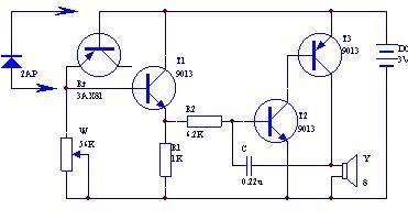
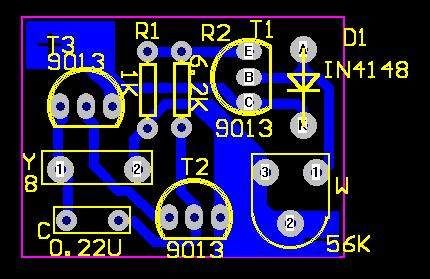
This water boiling alarm circuit consists of 4 triodes, whose circuit is shown in the figure. In the figure, the transistors T2 and T3, resistor R2 and capacitor C,etc, compose the audio oscillator, the audio signal is output from the loudspeaker. The transistor T1, resistors R1 and W, the transistor knot be and Rt, etc, compose a switch circuit as the switch of the oscillator. Rt is the temperature sensing element, which is equal to the bias resistor of T1. Usually, Rt is reversely blocked, T1 is also blocked; when the temperature is rising up, the reversal resistance of Rt is falling down, the current leakage is rising up.
(View)
View full Circuit Diagram | Comments | Reading(644)
The gas leakage alarm
Published:2011/7/4 6:14:00 Author:Borg | Keyword: gas leakage alarm
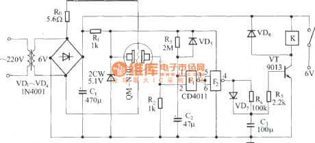
The gas sensor can form a gas leakage wireless remote control alarm, when the gas leakage is over the content of the safety standard, the sensor is outputting a detecting signal, and the wireless emitter circuit is emitting alarm signal after the signal is amplified and processed. In the figure is the gas leakage wireless remote control alarm which consists of the gas sensor(QM-N10), when the gas leakage is over the regulated standard, the relay will pull in and get the working power supply of the emitter circuit through. The emitter circuit of the alarm has not been drawn in the figure.
(View)
View full Circuit Diagram | Comments | Reading(1102)
The radar monitor language alarm
Published:2011/7/4 6:02:00 Author:Borg | Keyword: radar monitor, language alarm
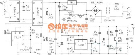
The circuit consists of the microwave sensing part TWH9248/TWH9249, single steady time delay circuit, language alarm circuit, FM emitter circuit and power supply circuit,etc.
(View)
View full Circuit Diagram | Comments | Reading(557)
The Smoking Ban and Fire Warning Board Circuit
Published:2011/7/4 6:20:00 Author:Borg | Keyword: Smoking Ban, Fire Warning
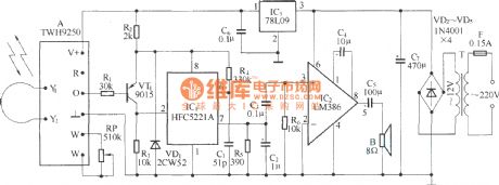
When someone walks past the valid range of the warning board, this circuit will make the sound of twang```no smoking, no fire . (View)
View full Circuit Diagram | Comments | Reading(620)
Benz SRS composition and installation location circuit
Published:2011/7/4 2:01:00 Author:Christina | Keyword: Benz, SRS, composition, installation, location circuit
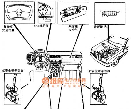
Benz SRS composition and installation location circuit
(View)
View full Circuit Diagram | Comments | Reading(477)
Benz W140 model SRS composition and installation location circuit
Published:2011/7/4 1:59:00 Author:Christina | Keyword: Benz, SRS, composition, installation location
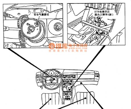
Benz W140 model SRS composition and installation location circuit
(View)
View full Circuit Diagram | Comments | Reading(668)
Powerhope UPS battery cannot charging maintenance circuit diagram
Published:2011/6/24 2:29:00 Author:Ecco | Keyword: Powerhope , UPS battery , cannot charging, maintenance
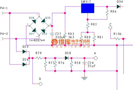
Repairing parts: 1. good or bad of four diodes D30, D31, D32, D33 in bridge rectifier; 2. leakage of filter capacitor C27 ; 3. good or bad of LM317; 4.LM317 external resistors R83, R80, R81, R82, R83, R86 is changing value or not; 5 charging diode D34 is good or bad.
(View)
View full Circuit Diagram | Comments | Reading(2238)
465kHz amplitude modulation intermediate frequency signal generator circuit
Published:2011/7/4 1:54:00 Author:Christina | Keyword: 465kHz, amplitude modulation, intermediate frequency, signal generator

The 465kHz amplitude modulation intermediate frequency signal generator circuit is as shown in the figure 1. The 400Hz low-frequency multivibrator is composed of the VT1 and VT2, the 465kHz intermediate frequency oscillator is composed of the VT3, VT4 and the ceramic filter 3L465. The 400Hz low-frequency modulates the 465KHZ intermediate frequency signal through C3, and the modulated 465kHz intermediate frequency signal is output by the emitter VT4. The ceramic filter of the circuit has the frequency selection function. The potentiometer RP can be used to adjust the output amplitude.
Figure 1 The 465kHz amplitude modulation intermediate frequency signal generator circuit
(View)
View full Circuit Diagram | Comments | Reading(2835)
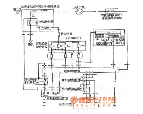
Accord 2003 vehicle cruise control circuit diagram
Published:2011/6/26 22:40:00 Author:Ecco | Keyword: Accord 2003 , vehicle , cruise control
View full Circuit Diagram | Comments | Reading(619)
16-pin diagnosis connector reading wiring circuit
Published:2011/7/4 1:56:00 Author:Christina | Keyword: 16-pin, diagnosis connector, reading, wiring circuit
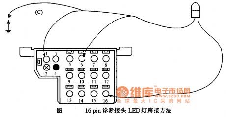
The 16-pin diagnosis connector reading wiring circuit
(View)
View full Circuit Diagram | Comments | Reading(604)
BENZ 560SL ABS system circuit
Published:2011/7/4 2:05:00 Author:Christina | Keyword: BENZ, ABS, system circuit
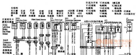
BENZ 560SL ABS system circuit
(View)
View full Circuit Diagram | Comments | Reading(564)
Non-Transformer Type Product Detection (MC1596G) Circuit Diagram
Published:2011/7/1 23:59:00 Author:Vicky | Keyword: Non-Transformer, Product Detection
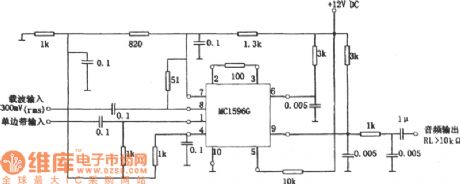
The above picture is a non-transformer type product detection circuit. The circuit uses MC1596G instead of LC resonance and transformer. The circuit is available in a frequency range from low frequency to a relative wide frequency of 100MHz, that is to say, it works by changing the parameter of RC low part filter in output part. The circuit is available in Mixer, Frequency Doubler, and modulator etc. (View)
View full Circuit Diagram | Comments | Reading(727)
| Pages:1630/2234 At 2016211622162316241625162616271628162916301631163216331634163516361637163816391640Under 20 |
Circuit Categories
power supply circuit
Amplifier Circuit
Basic Circuit
LED and Light Circuit
Sensor Circuit
Signal Processing
Electrical Equipment Circuit
Control Circuit
Remote Control Circuit
A/D-D/A Converter Circuit
Audio Circuit
Measuring and Test Circuit
Communication Circuit
Computer-Related Circuit
555 Circuit
Automotive Circuit
Repairing Circuit
