
Circuit Diagram
Index 1628
Mine electric coal drill security power controller circuit diagram
Published:2011/6/13 5:36:00 Author:Lucas | Keyword: Mine , electric coal drill , security power controller
The mine electric coal drill security power controller circuit is composed of the trigger control circuit, maintain control circuit and control implementation circuit, and the circuit is shown as the chart. Trigger control circuit is composed of the drill handle switch S, resistors R1 ~ R5, diodes VD1, VD2, capacitors C1, C2 and transistor V1. Maintain control circuit is composed of the current transformer TA, capacitors C3 ~ C5, diodes VD3, VD4, resistors R6, R7 and transistor V2. Control implementation circuit is composed of the resistors R8, R9, capacitor C6, transistor V3, diode VD5, AC contactor KM and relay K. R1 uses 1 ~ 2W metal film resistor; R2 ~ R9 select 1/4W metal film resistors.
(View)
View full Circuit Diagram | Comments | Reading(419)
Traffic light control circuit
Published:2011/6/29 20:07:00 Author:zj | Keyword: Traffic light, 74LS273, 74LS240

View full Circuit Diagram | Comments | Reading(2167)
Simplied Cable Quick Test (74HC4017) Circuit Diagram
Published:2011/6/26 0:53:00 Author:Vicky | Keyword: Simplied Cable Quick Test
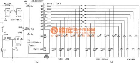
Cable Quick Test is mainly used to test the on-off situation of regional computer network cable and the analogous comprehensive digital cable and analog cable. It is much easier and quicker than multimeter. The circuit is divided into main circuit and remote circuit, so it can still be used to test even if the two ends of the cable are in different places. The main circuit constitutes a clock generating circuit which is composed of IC1 invert Schmidt trigger 74HC14 and a luminous diode LED sequent-lighting circuit which is compose of IC2. It is shown in picture(a). The roment circuit is shown in picuture (b). (View)
View full Circuit Diagram | Comments | Reading(2568)
Circuit Diagram of Frequency-Coversion Electromagnetic Dotting Timer composed of CD4017
Published:2011/6/26 0:52:00 Author:Vicky | Keyword: Frequency-Coversion Electromagnetic Dotting Timer
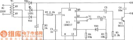
The main defection of electromagnetic dotting timer is the big shortfall. The reasons are: first, the needle of the electromagnetic dotting timer will cause rubbing effect to the recording paper when dotting and therefore make the moving speed of the paper slow down; second, the electromagnetic is driven by the AC whose voltage has been reduced, and time interval of the dotting is a cycle of alternative current, that is 0.02s.
The above circuit as shown in the picture adds a frequency-conversion power by making use of electronic crossover technique on the base of J0203-1 dotting timer commonly-used in senior schools so that the needle of J0203-1 dotting timer can timing with different cycles. (View)
View full Circuit Diagram | Comments | Reading(710)
Inductive Electricity Test Pencil (CD 4069) Circuit Diagram
Published:2011/6/23 8:41:00 Author:Vicky | Keyword: Inductive Electricity Test Pencil

IC1 is a hex inverter integrated circuit CD4069 and its inverter IC1-1 together with surrounding components constitutes a high input impendent and high gain voltage amplifier. The probe receives the weak electric field signal, sends it out after amplified by amplifier and
Control the post-stage circuit via inverter IC1-2. Inverters IC1-5, IC-6, resistance R5 and capacitance C2 constitute the multivibrator, whose work is controlled by the working state of inverter ICl-3. When the probe detects signal, IC1-3 sends out high level, the diode VDI ends, and oscillator works and make the piezoelectric ceramics HTD give out sounds. Meanwhile inverter IC1-4 sends out high level, triode VTI is conducted, red luminous diode LED2 lightens which represents the guide line under test is electrified. (View)
View full Circuit Diagram | Comments | Reading(3093)
Voltage-Regulator Diode Performance Quick Test Circuit Diagram
Published:2011/6/26 6:12:00 Author:Vicky | Keyword: Voltage-Regulator Diode Performance Quick Test

As shown in the picture, VT1 & VT2 etc constitute astable free-running multivibrator and the vibrator’s frequency is determined by C1, R2,R3, C2 etc. The cycle of the vibrator is about 4 seconds. VT2 gives out high level, the level then is transformed by VD, and VT3 is conducted, meanwhile the current is limited by luminous diode H1 and resistance R6, and finally it triggers bidirectional diode thyristor. A good thyristor is immediately conducted, and luminous diode H2 gives out light; when VT2 gives lout low level, VD, VT3, VS all end and H2 is lightless. If H1 and H2 shines synchronously , the thyristor is good; if H1 shines while H2 is extinct, then VS suffers internal short-circuit; if H2 remains luminous all the time, then VS suffers internal breakdown; if both H1 and H2 don’t shine, then VT1 and VT2 circuit don’t vibrate. (View)
View full Circuit Diagram | Comments | Reading(813)
Resistance Quick Tester Diagram Circuit
Published:2011/6/16 10:52:00 Author:Vicky | Keyword: Resistance Quick Tester

The above picture is the Quick Resistance Tester Diagram Circuit. The core of the circuit is multivibrator composed of 555, R1, R2, R3, Rx (resistance under test) and C1. Resistances numbered from R4 to R9 are known resistance of the tester.
A circle of the multivibrator output signal is T=0.693[R1+2(R2+R3Rx/(R3+Rx))].The frequency of the multivibrator can be changed when the position of gating switch K is changed, and thus signal of different tones is given out from the speaker. Because the resistance values of resistances numbered from R4 to R9 are known and Rx is a to-be-tested resistance, it is easy and quick to estimate the range og resistance value of the resistance under test by comparing with the loudness level of the know resistances’ corresponding oscillator frequency.
(View)
View full Circuit Diagram | Comments | Reading(639)
MG45 & MG44 resin package circuit
Published:2011/7/4 20:21:00 Author:Christina | Keyword: resin package

View full Circuit Diagram | Comments | Reading(978)
TMPA8807PSN Multi-Function Super Monolithic Circuit Diagram
Published:2011/7/3 2:38:00 Author:Vicky | Keyword: Multi-Function, Super Monolithic

Internal Block Circuit Diagram and Typical Applied Circuit
TMPA8807PSN is a television multi-function super-monolithic integrated circuit produced by Toshiba Corporation. It is widely used in large-screen color television set of Kongka series, TCL series, Haier series, Toshiba series, Hisense Serires, and Changhong series etc.
1 functions and features
IC TMPA8807PSN includes microprocessor, television small-signal processing circuit, teletext decoder circuit and some other accessory functional circuit.
2 functions and datum of pins
ICPA8807PSN uses 64 pins which are in dual-in-line package. It is available in PAL, NTSC and SECAM.
3 typical applied circuit
The internal block circuit diagram and typical applied circuit is shown in the above picture.
(View)
View full Circuit Diagram | Comments | Reading(723)
MC68HCO5B6 Single-Chip Micro-Computer Integrated Circuit
Published:2011/7/3 2:11:00 Author:Robert | Keyword: Single-Chip, Micro-Computer, Integrated


The MC68HCO5B6 is a single-chip micro-computer control IC produced by the American Motorola company which is widely used in automatical washing machine such as the Cygnet XQB40-868FG type automatical washing machine and so on.
1.Its functional features.
The MC68HCO5B6 IC has internal central processing unit (CPU), key scanning coding circuit, display decoding and driving circuit, clock oscillation circuit, reset control circuit, A/D and D/A converting circuit, water-inflow detecting and control circuit, washing capacity detecting circuit, washing motor control circuit, timing/counting alarm circuit and some other kinds of ancillary circuits.
2.Its pin's functions.
The MC68HCO5B6 IC uses 56-pin dual inline package. Its pin's functions is listed in the table and its internal circuit diagram is shown in the picture (b).
The table shows the MC68HCO5B6 IC's pin's functions. (View)
View full Circuit Diagram | Comments | Reading(685)
QM Series Gas Sensor Shape Circuit
Published:2011/7/3 5:50:00 Author:Robert | Keyword: Gas, Sensor, Shape
The picture shows the QM series gas sensor shape. (View)
View full Circuit Diagram | Comments | Reading(811)
D371 Cellphone Boost Driving Integrated Circuit
Published:2011/7/4 7:20:00 Author:Robert | Keyword: Cellphone, Boost, Driving, Integrated

The D371 is a cellphone boost driving IC which is used in many brands of cellphones, such as the TCL series cellphones.
1.Its functional features.
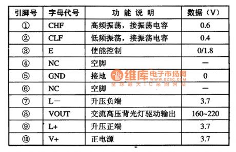
The D371 IC has internal oscillation circuit, boost circuit, high-voltage backlight driving circuit and so on. Its function is transforming the cellphone's about 3V DC voltage to 160-220V high-frequency AC voltage, so that it would drive the EL backlight.
2.Its pin's function and data.
The D371 IC uses 10-pin package and its pin's function and data is listed in table 1.
The table 1 shows the D371 IC's pin's function and data.
3.Typical application circuit.
The EL backlight typical application circuit composed of D371 IC is shown in picture 1.
The picture 1 shows the D371 IC's typical application circuit. (View)
View full Circuit Diagram | Comments | Reading(573)
KD0071 IC Typical Application Circuit
Published:2011/7/4 7:46:00 Author:Robert | Keyword: IC, Typical, Application

The KD0071 is a single-chip sound-conversion IC which is adequate for the sound generating circuits in many kinds of toys and Kara OK'a tonal modification.
The KD0071 IC has internal oscillation circuit, trigger circuit, A/D (analog/digital) conversion circuit, and other some auxiliary circuits.
The sound-conversion circuit typical application circuit composed of KD0071 IC is shown in the picture.
It should be noted that SA3 is the control switch of the robot's sound effect. When it is closed the speaker would play the sound of the robot sound effect.
The SB is sound effect conversion switch. Each time it is pressed the sound effect would has a conversion.
The R4, C8 is frequency-selecting elements of the oscillation clock.
The picture shows the KD0071 IC's typical application circuit. (View)
View full Circuit Diagram | Comments | Reading(1028)
Color TV Sets Remote-Control System Integrated Circuit
Published:2011/7/4 8:22:00 Author:Robert | Keyword: Color, TV Sets, Remote-Control, System, Integrated

The table shows the color TV sets remote-control system IC's functions and models.
The color TV sets remote-control IC' functions and models are listed in the table. (View)
View full Circuit Diagram | Comments | Reading(713)
TV Sets Application Integrated Circuit
Published:2011/7/4 8:18:00 Author:Robert | Keyword: TV Sets, Application, Integrated


The table shows the common-using IC's models and functions in the color TV sets.
The color TV sets' common-using IC's models and functions are listed in the table. (View)
View full Circuit Diagram | Comments | Reading(647)
CX7959 Memory Integrated Circuit
Published:2011/7/4 8:31:00 Author:Robert | Keyword: Memory, Integrated


The CX7959 is a memory IC produced by the Japanese Sony company. It is widely used in the Sony series color TV sets and the derived products.
1.Its functional features.
The CX7959 IC has internal memory matrix circuit, input/output interface circuit, testing circuit and so on.
2.Its pin's function and data.The CX7959 IC uses 14-pin dual package. Its pin's functions are shown in picture 1 and its working parameters are listed in table 1.The picture 1 shows the CX7959 IC's pin's functions.The table 1 shows the CX7959's working parameters. (View)
View full Circuit Diagram | Comments | Reading(1002)
Structure circuit of the photosensitive diode
Published:2011/7/3 22:16:00 Author:Christina | Keyword: Structure circuit, photosensitive diode
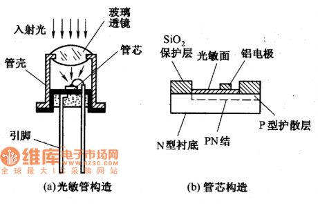
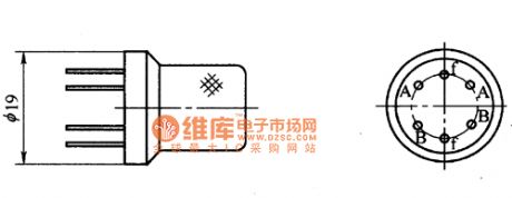
The photosensitive diode is also called photoelectric diode, it has the same structure with the general semiconductor diode. The figure shows the structure of the photosensitive diode. There is a glass lens on the photodiode shell, the incident light is shining on the tube core through the glass lens. The tube core of the light-emitting diode is the PN junction with the photosensitive properties, it is packaged in the tube shell. The photosensitive surface of the light-emitting diode is the film of the N-type silicon. The PN junction of the light-emitting diode's core and the core itself have large area, but the electrode area of the tube core is small.
(View)
View full Circuit Diagram | Comments | Reading(926)
2CR series silicon blue-ray battery appearance circuit
Published:2011/7/4 4:14:00 Author:Christina | Keyword: 2CR series, silicon, blue-ray battery, appearance circuit

2CR series silicon blue-ray battery appearance circuit
(View)
View full Circuit Diagram | Comments | Reading(561)
1-20MHz quartz crystal oscillator circuit
Published:2011/7/4 4:12:00 Author:Christina | Keyword: 1-20MHz, quartz crystal, oscillator

The quartz crystal oscillator circuit which is composed of the quartz crystal resonator and the coupling capacitance of the multivibrator is as shown in figure 1. This oscillation frequency of this circuit depends on the resonant frequency of the quartz crystal, and it has nothing to do with the R, C components of the circuit, you just need to change the quartz crystal resonator, so you can select the oscillation frequency of the oscillator in the range of 1-2OMHz.
Figure 1 The 1~2OMHz quartz crystal oscillator circuit
(View)
View full Circuit Diagram | Comments | Reading(2856)
2CR series silicon blu-ray battery typical application circuit
Published:2011/7/4 4:05:00 Author:Christina | Keyword: 2CR series, silicon, blu-ray battery, typical application circuit

2CR series silicon blu-ray battery typical application circuit
(View)
View full Circuit Diagram | Comments | Reading(531)
| Pages:1628/2234 At 2016211622162316241625162616271628162916301631163216331634163516361637163816391640Under 20 |
Circuit Categories
power supply circuit
Amplifier Circuit
Basic Circuit
LED and Light Circuit
Sensor Circuit
Signal Processing
Electrical Equipment Circuit
Control Circuit
Remote Control Circuit
A/D-D/A Converter Circuit
Audio Circuit
Measuring and Test Circuit
Communication Circuit
Computer-Related Circuit
555 Circuit
Automotive Circuit
Repairing Circuit