Control Circuit
Water level control circuit
Published:2011/7/2 21:28:00 Author:Lucas | Keyword: Water level , control | From:SeekIC


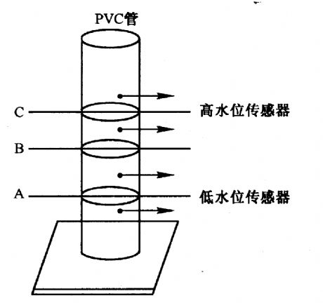
Figure 2-23 (a) shows the sensor. There are two pairs of wires being installed in the corresponding water level A and C inside of the PVC pipe, only when the water level rises more than A, B and C, the pump will stop running. When the water level drops below the C and B, pump will maintain working. Only when the water level is lower than A, the pump is switched on to run. Figure 2-23 (b) shows the pump motor control circuit. In the circuit, Al-A4 use 5V single supplied TLC2274 op amp. Among them, Al and A2 form the comparator to control D flip-flop 7474 and add the reference voltage with about 4V at inverting input end of A3 and A4.
Reprinted Url Of This Article:
http://www.seekic.com/circuit_diagram/Control_Circuit/Water_level_control_circuit.html
Print this Page | Comments | Reading(3)

Article Categories
power supply circuit
Amplifier Circuit
Basic Circuit
LED and Light Circuit
Sensor Circuit
Signal Processing
Electrical Equipment Circuit
Control Circuit
Remote Control Circuit
A/D-D/A Converter Circuit
Audio Circuit
Measuring and Test Circuit
Communication Circuit
Computer-Related Circuit
555 Circuit
Automotive Circuit
Repairing Circuit
Code: