Basic Circuit
Electric welding machine no load electricity saver 7
Published:2011/6/30 21:10:00 Author:Nicole | Keyword: electric welding machine, electricity saver | From:SeekIC

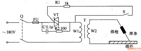
The electric welding machine no load electricity saver circuit is composed of control power transformer T1, intermediate relay KA, relay KT, AC contactor KM, potentiometer RP and indication light HL1, HL2, it is shown in the figure 8-11.
After knife switch Q is turned on, T1 works, power indication light HL1 lights. When welding, below, intermediate relays KA pull in, the normally open contact KA1, KA2 are turned on, then KKM's normally open contact KM1, KM2 are turned on, the normally closed contact KM3 and KM4 are cut off, it works, it shows it can do welding.
Reprinted Url Of This Article:
http://www.seekic.com/circuit_diagram/Basic_Circuit/Electric_welding_machine_no_load_electricity_saver_7.html
Print this Page | Comments | Reading(3)

Article Categories
power supply circuit
Amplifier Circuit
Basic Circuit
LED and Light Circuit
Sensor Circuit
Signal Processing
Electrical Equipment Circuit
Control Circuit
Remote Control Circuit
A/D-D/A Converter Circuit
Audio Circuit
Measuring and Test Circuit
Communication Circuit
Computer-Related Circuit
555 Circuit
Automotive Circuit
Repairing Circuit
Code: