Basic Circuit
Electric welding machine no load electricity saver 6
Published:2011/6/30 21:00:00 Author:Nicole | Keyword: electric welding machine, electricity saver | From:SeekIC

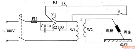
The electric welding machine no load electricity saver circuit is composed of knife switch Q, fuse FU, capacitor C, resistors R1, R2, thyristor VT, electric welding machine transformer T and trigger switch S, it is shown in the figure 8-10.
When knife switch Q is turned on, 380V AC voltage is added to T's circuit by Q(the circuit is made of FU, VT, C, R2 and winding W1). When trigger switch S is not turned on, VT is in off state, C, R2 are connected into the circuit, then the electric welding machine is in electricity saving state, the current which flows T's loop is smaller.
Reprinted Url Of This Article:
http://www.seekic.com/circuit_diagram/Basic_Circuit/Electric_welding_machine_no_load_electricity_saver_6.html
Print this Page | Comments | Reading(3)

Article Categories
power supply circuit
Amplifier Circuit
Basic Circuit
LED and Light Circuit
Sensor Circuit
Signal Processing
Electrical Equipment Circuit
Control Circuit
Remote Control Circuit
A/D-D/A Converter Circuit
Audio Circuit
Measuring and Test Circuit
Communication Circuit
Computer-Related Circuit
555 Circuit
Automotive Circuit
Repairing Circuit
Code: