Basic Circuit
Electric welding machine no load electricity saver 8
Published:2011/6/30 21:30:00 Author:Nicole | Keyword: electric welding machine, electricity saver | From:SeekIC

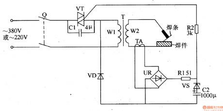
The electric welding machine no load electricity saver circuit is composed of knife switch Q, relays K1, K2, intermediate relay KA, AC contactor KM, time relay KT, reed switch SA, diodes VD1, VD2, indication light HL, resistor R, capacitors C1-C3, potentiometers RP1, RP2 and electric welding machine transformer T, it is shown in the figure 8-12.
When KM pulls in, but it is not welded, the induced voltage which produced by the both sides of T's secondary winding is rectified by VD2 and then it is added to K2, K2 is pulled in, K2's normally open contact is turned on, KT pulls in and it starts to timing.
Reprinted Url Of This Article:
http://www.seekic.com/circuit_diagram/Basic_Circuit/Electric_welding_machine_no_load_electricity_saver_8.html
Print this Page | Comments | Reading(3)

Article Categories
power supply circuit
Amplifier Circuit
Basic Circuit
LED and Light Circuit
Sensor Circuit
Signal Processing
Electrical Equipment Circuit
Control Circuit
Remote Control Circuit
A/D-D/A Converter Circuit
Audio Circuit
Measuring and Test Circuit
Communication Circuit
Computer-Related Circuit
555 Circuit
Automotive Circuit
Repairing Circuit
Code: