Signal Processing
Heart Rhythm Tester (the 3rd)
Published:2011/6/23 21:39:00 Author:Felicity | Keyword: Heart Rhythm Tester (the 3rd) | From:SeekIC

Work of the circuit
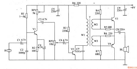
The circuit consists of sensor B, pre-amplifying circuit, low frequency amplifying circuit and capacity amplifying circuit. (It is shows in picture 9-55.)
When you use the tester, put it on the heart area. Use hands to fix it. B changes the sound of hearting beating into electronic signal. The electronic signal is pre-amplified by V1, sound controlled by RP2, low frequency amplified by V2 and capacity amplified by V3, V3. The amplifier BL will play the amplified sound of heart beating.
Reprinted Url Of This Article:
http://www.seekic.com/circuit_diagram/Signal_Processing/Heart_Rhythm_Tester_the_3rd.html
Print this Page | Comments | Reading(3)

Article Categories
power supply circuit
Amplifier Circuit
Basic Circuit
LED and Light Circuit
Sensor Circuit
Signal Processing
Electrical Equipment Circuit
Control Circuit
Remote Control Circuit
A/D-D/A Converter Circuit
Audio Circuit
Measuring and Test Circuit
Communication Circuit
Computer-Related Circuit
555 Circuit
Automotive Circuit
Repairing Circuit
Code: