
Circuit Diagram
Index 1646
The 15V regulated power supply circuit of SCR
Published:2011/6/30 22:11:00 Author:qqtang | Keyword: regulated power supply

View full Circuit Diagram | Comments | Reading(913)
The auto temperature control circuit
Published:2011/6/30 21:27:00 Author:qqtang | Keyword: temperature control

The figured circuit consists of the temperature control sensor switch, the temperature LED display circuit of upper and lower limit, SCR control circuit, analog sound circuit and AC step-down rectifier circuit, etc. The temperature circuit can do the auto control in the within the upper and lower temperature, the detecting precision is ±3℃, so the effect is ideal, and it can also indicate the over-temperature.
(View)
View full Circuit Diagram | Comments | Reading(566)
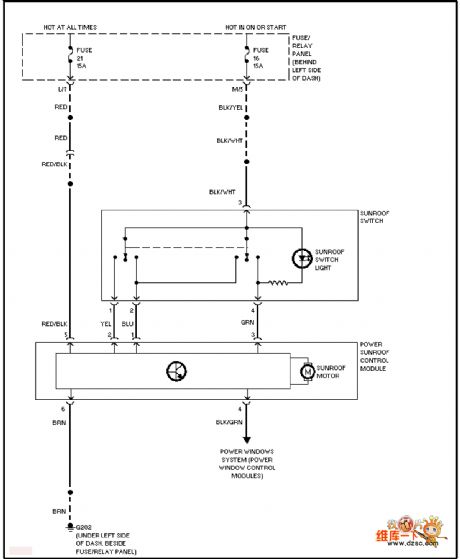
The Volkswagon sunshade tent circuit
Published:2011/6/30 21:52:00 Author:qqtang | Keyword: Volkswagon, sunshade tent
View full Circuit Diagram | Comments | Reading(462)
The 5V-+12V and -15V DC converter circuit
Published:2011/6/30 20:38:00 Author:qqtang | Keyword: DC converter

Figure: The 5V-+12V and -15V DC converter circuit (View)
View full Circuit Diagram | Comments | Reading(1667)
The auto power regulation temperature controller circuit
Published:2011/6/30 20:43:00 Author:qqtang | Keyword: auto power regulation, temperature controller

The temperature controller can adjust the input power of the heater while the LED is indicating the temperature range, which makes the controlled heater in constant working temperature state. The circuit is shown in the figure.
(View)
View full Circuit Diagram | Comments | Reading(913)
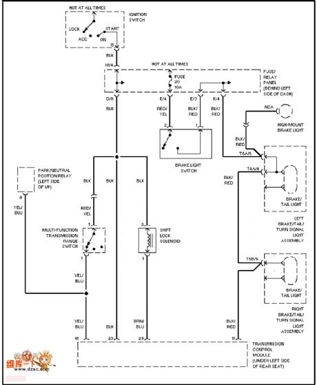
The Volkswagon gear shift interlock circuit
Published:2011/6/30 21:51:00 Author:qqtang | Keyword: Volkswagon, gear shift, interlock
View full Circuit Diagram | Comments | Reading(639)
Photoelectric-Type Auto-Counting Device Circuit Diagram
Published:2011/6/23 8:49:00 Author:Vicky | Keyword: Photoelectric-Type Auto-Counting Device

The principle of photoelectric-type auto-counting device is shown in the picture. It is made of single chip microcomputer PIC16C57, which is applicable to industry automatic control of product line and of certain practical value. (View)
View full Circuit Diagram | Comments | Reading(1658)
The 50w DC transformer circuit
Published:2011/6/30 20:44:00 Author:qqtang | Keyword: DC transformer

Figure:The 50w DC transformer circuit (View)
View full Circuit Diagram | Comments | Reading(511)
The auto sequence connecting power supply control ciruit
Published:2011/6/30 20:47:00 Author:qqtang | Keyword: sequence, power supply control

View full Circuit Diagram | Comments | Reading(627)
The South-east Wagon central control and warning equipment system circuit
Published:2011/6/30 20:53:00 Author:qqtang | Keyword: central control, warning equipment system
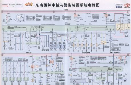
The South-east Wagon central control and warning equipment system circuit is shown as above.
(View)
View full Circuit Diagram | Comments | Reading(489)
The Volkswagon anti-burglar circuit
Published:2011/6/30 20:48:00 Author:qqtang | Keyword: Volkswagon, anti-burglar circuit

View full Circuit Diagram | Comments | Reading(851)
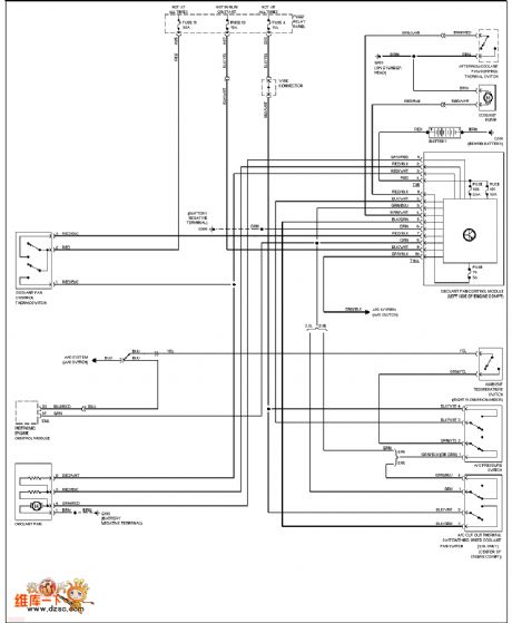
The Guangzhou Honda charging system circuit
Published:2011/6/30 20:55:00 Author:qqtang | Keyword: Guangzhou Honda, charging system

The Guangzhou Honda charging system circuit is shown in the figure.
(View)
View full Circuit Diagram | Comments | Reading(612)
The Volkswagon charging system circuit
Published:2011/6/30 20:50:00 Author:qqtang | Keyword: Volkswagon, charging system

View full Circuit Diagram | Comments | Reading(604)
The auto control circuit of over-temperature detection
Published:2011/6/30 21:00:00 Author:qqtang | Keyword: control circuit, over-temperature detection

The circuit consists of a NAND circuit, a detection circuit composed of thermistor and a alarm sound generating circuit, and the relay is the executing circuit. Its structure is simple and it's low-cost. The circuit is shown in the figure.
(View)
View full Circuit Diagram | Comments | Reading(884)
The randomly set standby power supply voltage circuit
Published:2011/6/30 21:03:00 Author:qqtang | Keyword: standby power supply, voltage circuit

View full Circuit Diagram | Comments | Reading(636)
The Great Wall-Harvard central lock, airbag, ABS, instruments and lighting system circuit
Published:2011/6/30 21:09:00 Author:qqtang | Keyword: central lock, airbag, ABS, instruments, lighting system
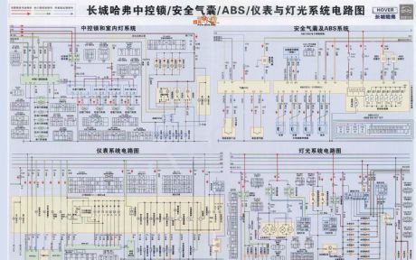
The Great Wall-Harvard central lock, airbag, ABS, instruments and lighting system circuit is shown in the figure.
(View)
View full Circuit Diagram | Comments | Reading(1094)
Circuit Diagram of digital eight-way disconnection detector composed of monolithic 89C2051
Published:2011/6/23 8:44:00 Author:Vicky | Keyword: digital eight-way disconnection detector
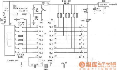
View full Circuit Diagram | Comments | Reading(567)
The Volkswagon cooling fan circuit
Published:2011/6/30 21:04:00 Author:qqtang | Keyword: Volkswagon, cooling fan
View full Circuit Diagram | Comments | Reading(436)
FM/FSK 433MHz Emitter Circuit Diagram
Published:2011/6/19 7:03:00 Author:Vicky | Keyword: FM/FSK 433MHz Emitter Circuit

Circuit of TRF4400 application in 433 MHz IS
TRF4400 is an multi-chanell low-cost emitter which can provide full functions. The can meet the requirement of 433MHz frequency band linear (FM) or application of digital(FSK) emitter.
Main technical features are listed as follows:
·Work frequency: 420~450 MHz;
·FM/FSK modulation mode;
·Small demand of exterior fittings;
·Work voltage: 2.2~3.6 V;
·Typical emitting power: 7 dBm;
·Maximum work current of emitter: 75 mA,low-power dissipation mode: 0.5μA;
·Flexible serial interface to be connected to T1 MSP430 microcontroller.
(View)
View full Circuit Diagram | Comments | Reading(1062)
MHz-KH Series Encoding Emitter Module Circuit Diagram
Published:2011/6/26 8:03:00 Author:Vicky | Keyword: MHz-KH Series Encoding Emitter Module
\TXE-433/418/315 MHz—KH series encoding emitter module
TXE-433/418/315 MHz—KH series encoding emitter module , when used together with KH decoding receptor module, can form a highly-reliable wireless link, which send 1 to 8 parallel input states; the address coding is 310 groups; the transmitting distance is over 91.5 m(300 ft). The correspondent receptors are RXD-315-KH(315 MHz)、RXD-418-KH(418 MHz)和RXD-433-KH(433 MHz).
KH series radio frequency encoding emitter is available in remote control system , keyless entering system, garage gate control, lightening control system etc.
Main technical features are listed below:
·No need of other exterior radio frequency component except antenna;
·Maximum output power: +4 dBm;
·Emitting data length: 26 bytes×3
·Work voltage: 2.7~5.2 V;
·Work current: l.5 mA,sleeping mode current: lμA。
(View)
View full Circuit Diagram | Comments | Reading(572)
| Pages:1646/2234 At 2016411642164316441645164616471648164916501651165216531654165516561657165816591660Under 20 |
Circuit Categories
power supply circuit
Amplifier Circuit
Basic Circuit
LED and Light Circuit
Sensor Circuit
Signal Processing
Electrical Equipment Circuit
Control Circuit
Remote Control Circuit
A/D-D/A Converter Circuit
Audio Circuit
Measuring and Test Circuit
Communication Circuit
Computer-Related Circuit
555 Circuit
Automotive Circuit
Repairing Circuit