Control Circuit
Loom saves electricity controller 4
Published:2011/6/29 21:55:00 Author:Nicole | Keyword: loom, saves electricity controller | From:SeekIC

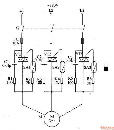
The loom saves electricity controller circuit is composed of knife switch Q, fuse FU, transistors VT1-VT3, resistors R1-R6, capacitors C1-C3, spring tubes SA1-SA2 and motor M, it is shown in the figure 8-20.
Knife switch Q is turned on, the loom's machine open and shut down handle is pushed blak of the start-up position, under the magneticaction of machine open and shut down handle's permanent magnet, the spring tubes SA1-SA2's control contact is connected, VT1-VT3 are triggered and turned on, motor M runs.
The sensitivity of V1-V3 trigger can be changed by adjusting R2, R4 and R6.
Reprinted Url Of This Article:
http://www.seekic.com/circuit_diagram/Control_Circuit/Loom_saves_electricity_controller_4.html
Print this Page | Comments | Reading(3)

Article Categories
power supply circuit
Amplifier Circuit
Basic Circuit
LED and Light Circuit
Sensor Circuit
Signal Processing
Electrical Equipment Circuit
Control Circuit
Remote Control Circuit
A/D-D/A Converter Circuit
Audio Circuit
Measuring and Test Circuit
Communication Circuit
Computer-Related Circuit
555 Circuit
Automotive Circuit
Repairing Circuit
Code: