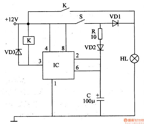
Control Circuit
Brake Flash Light
Published:2011/6/30 6:09:00 Author:Sue | Keyword: Brake, Flash, Light | From:SeekIC

When the oscillator begins to work, 300V high-frequency pulse voltage will be generated on W3. The voltage will be divided into four circuits after rectification. One will be put on the flash light's A terminal directly. One will charge C4. One will charge C3 through R2,R3. One will charge C2 through R2,R4,R5.
When C2-C4 stop charging, V2, VT will be connected. C3 will generate high voltage on T2. The voltage will be put on B,C. Then C2-C4 will be charged quickly. Everytime the brake switch is connected, the flash light will twinkle many times.
Reprinted Url Of This Article:
http://www.seekic.com/circuit_diagram/Control_Circuit/Brake_Flash_Light.html
Print this Page | Comments | Reading(3)

Article Categories
power supply circuit
Amplifier Circuit
Basic Circuit
LED and Light Circuit
Sensor Circuit
Signal Processing
Electrical Equipment Circuit
Control Circuit
Remote Control Circuit
A/D-D/A Converter Circuit
Audio Circuit
Measuring and Test Circuit
Communication Circuit
Computer-Related Circuit
555 Circuit
Automotive Circuit
Repairing Circuit
Code: