Control Circuit
The electric over-voltage relay circuit
Published:2011/7/3 7:31:00 Author:Borg | Keyword: over-voltage relay | From:SeekIC
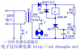
The electric over-voltage relay circuit The circuit is simple, when the power supply voltage is over the limit value, it will take action, the power supply is cut off, which makes sure the load won't be two high. The power supply of the relay and the controllable silicon is turned into 24V by the transformer, and then rectified by D1, the relay and the controllable silicon are connected together in the parallel way. R1 and R2 are the distributing resistors, the control pole LEV can be controlled by adjusting R2, so the SCR can be conducting in the selected voltage. When the power supply voltage reaches the limit value of the SCR, the SCR is conducting.
Reprinted Url Of This Article:
http://www.seekic.com/circuit_diagram/Control_Circuit/The_electric_over_voltage_relay_circuit.html
Print this Page | Comments | Reading(3)

Article Categories
power supply circuit
Amplifier Circuit
Basic Circuit
LED and Light Circuit
Sensor Circuit
Signal Processing
Electrical Equipment Circuit
Control Circuit
Remote Control Circuit
A/D-D/A Converter Circuit
Audio Circuit
Measuring and Test Circuit
Communication Circuit
Computer-Related Circuit
555 Circuit
Automotive Circuit
Repairing Circuit
Code: