555 Circuit
555 simplified double wires logical state judge circuit
Published:2011/6/12 9:22:00 Author:nelly | Keyword: simplified double wires, logical state | From:SeekIC


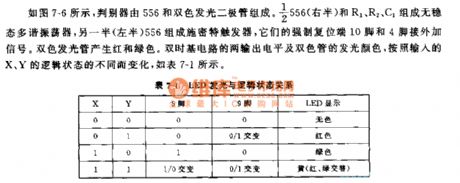
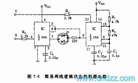
As shown on the figure 7-6, the judger consists of the 556 anddouble-color LED. The actable multivibrator consists of the the right side of 556 and R1,R2,C1. The left side of 556 makes up of the Schmitt trigger. Their 10 foot and 4 foot contact external signal. The double-color LED produces red and green light. The dual time base circuit's output level and the double color CRT's color-emitting change with the logical state of the X and Y.
Reprinted Url Of This Article:
http://www.seekic.com/circuit_diagram/555_Circuit/555_simplified_double_wires_logical_state_judge_circuit.html
Print this Page | Comments | Reading(3)

Article Categories
power supply circuit
Amplifier Circuit
Basic Circuit
LED and Light Circuit
Sensor Circuit
Signal Processing
Electrical Equipment Circuit
Control Circuit
Remote Control Circuit
A/D-D/A Converter Circuit
Audio Circuit
Measuring and Test Circuit
Communication Circuit
Computer-Related Circuit
555 Circuit
Automotive Circuit
Repairing Circuit
Code: