Automotive Circuit
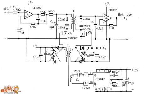
The FET wave chopping transformer coupling separating amplifier circuit
Published:2011/7/2 2:12:00 Author:Borg | Keyword: transformer, separating amplifier circuit | From:SeekIC

In the figure is the FET wave chopping transformer coupling separating amplifier circuit. The 1~5V DC input signal is impedance-converted by the buffer amplifier A1, and then turned into the AC signal by VT1 chopper, the AC signal is sent to the second stage by transformer T1. After that, it engages in the VT2 ON/OFF control at the second stage and it is rectified synchronously, and then it is changed in to a DC voltage signal which is proportional to the DC voltage signal.
In the circuit, TC4047 composes the multi-resonance oscillator, which generates the 25kHz square wave, and the wave motivates the driver TC426 of VT1 and VT2.
Reprinted Url Of This Article:
http://www.seekic.com/circuit_diagram/Automotive_Circuit/The_FET_wave_chopping_transformer_coupling_separating_amplifier_circuit.html
Print this Page | Comments | Reading(3)

Article Categories
power supply circuit
Amplifier Circuit
Basic Circuit
LED and Light Circuit
Sensor Circuit
Signal Processing
Electrical Equipment Circuit
Control Circuit
Remote Control Circuit
A/D-D/A Converter Circuit
Audio Circuit
Measuring and Test Circuit
Communication Circuit
Computer-Related Circuit
555 Circuit
Automotive Circuit
Repairing Circuit
Code: