Signal Processing
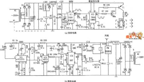
The infrared monitor wireless alarm circuit
Published:2011/7/1 22:17:00 Author:Borg | Keyword: infrared monitor, wireless alarm | From:SeekIC

In the figure is the infrared monitor wireless alarm circuit. The circuit consists of the infrared monitoring emitter and the infrared reception circuit, two parts in total, which are shown in figure (a) and figure (b) respectively. Figure (a) adopts two CMOS 555 chips (or one 556), IC1 and IC2, the two outputs the waveforms of 1.5KHz and 35KHz respectively, of which the 1.5KHz square wave is used to modulate the loading wave. In the figure, IC1 is connected as a multi-resonance oscillator, whose oscillating frequency is 1.5KHz, and the corresponding charge/discharge time is decided by the time constant. The duty cycle of the square wave output by IC1 is 1:3 (160μs:500μs).
Reprinted Url Of This Article:
http://www.seekic.com/circuit_diagram/Signal_Processing/The_infrared_monitor_wireless_alarm_circuit.html
Print this Page | Comments | Reading(3)

Article Categories
power supply circuit
Amplifier Circuit
Basic Circuit
LED and Light Circuit
Sensor Circuit
Signal Processing
Electrical Equipment Circuit
Control Circuit
Remote Control Circuit
A/D-D/A Converter Circuit
Audio Circuit
Measuring and Test Circuit
Communication Circuit
Computer-Related Circuit
555 Circuit
Automotive Circuit
Repairing Circuit
Code: