Control Circuit
Motor voltage reducing starter 1
Published:2011/6/29 20:24:00 Author:Nicole | Keyword: motor, voltage reducing starter | From:SeekIC
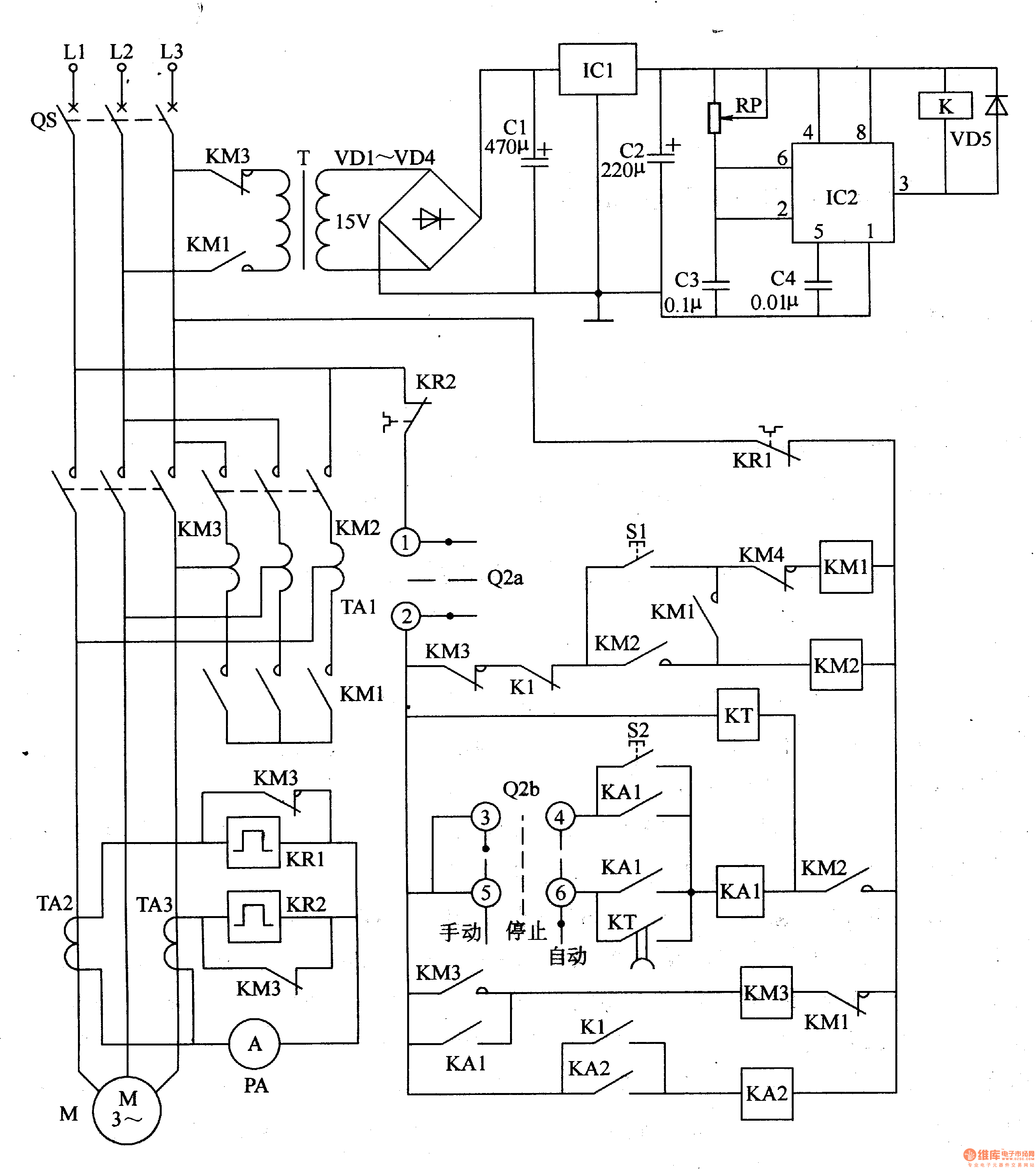
The motor voltage reducing starter is composed of voltage reducing starter control circuit and protection circuit, it is shown in the figure 8-55.
The voltage reducing starter control circuit is made of starter button S1, master controller(Q2a, Q2b), AC contactor KMl-KM3, intermediate relay KA1, KA2, time relay KT, autotransformer TA1.
The protection circuit consists of power transformer T, diodes VDl-VD5, capacitors C1-C3, there terminals steady voltage integrated circuit IC1, potentiometer RP, time base integrated circuit IC2 and relay K.
TA2, TA3 are current transformers, KR1 and KR2 are heat relays, QS is circuit breaker.
Reprinted Url Of This Article:
http://www.seekic.com/circuit_diagram/Control_Circuit/Motor_voltage_reducing_starter_1.html
Print this Page | Comments | Reading(3)

Article Categories
power supply circuit
Amplifier Circuit
Basic Circuit
LED and Light Circuit
Sensor Circuit
Signal Processing
Electrical Equipment Circuit
Control Circuit
Remote Control Circuit
A/D-D/A Converter Circuit
Audio Circuit
Measuring and Test Circuit
Communication Circuit
Computer-Related Circuit
555 Circuit
Automotive Circuit
Repairing Circuit
Code: