Control Circuit
Motor voltage reducing starter 2
Published:2011/6/29 20:54:00 Author:Nicole | Keyword: motor, voltage reducing starter | From:SeekIC
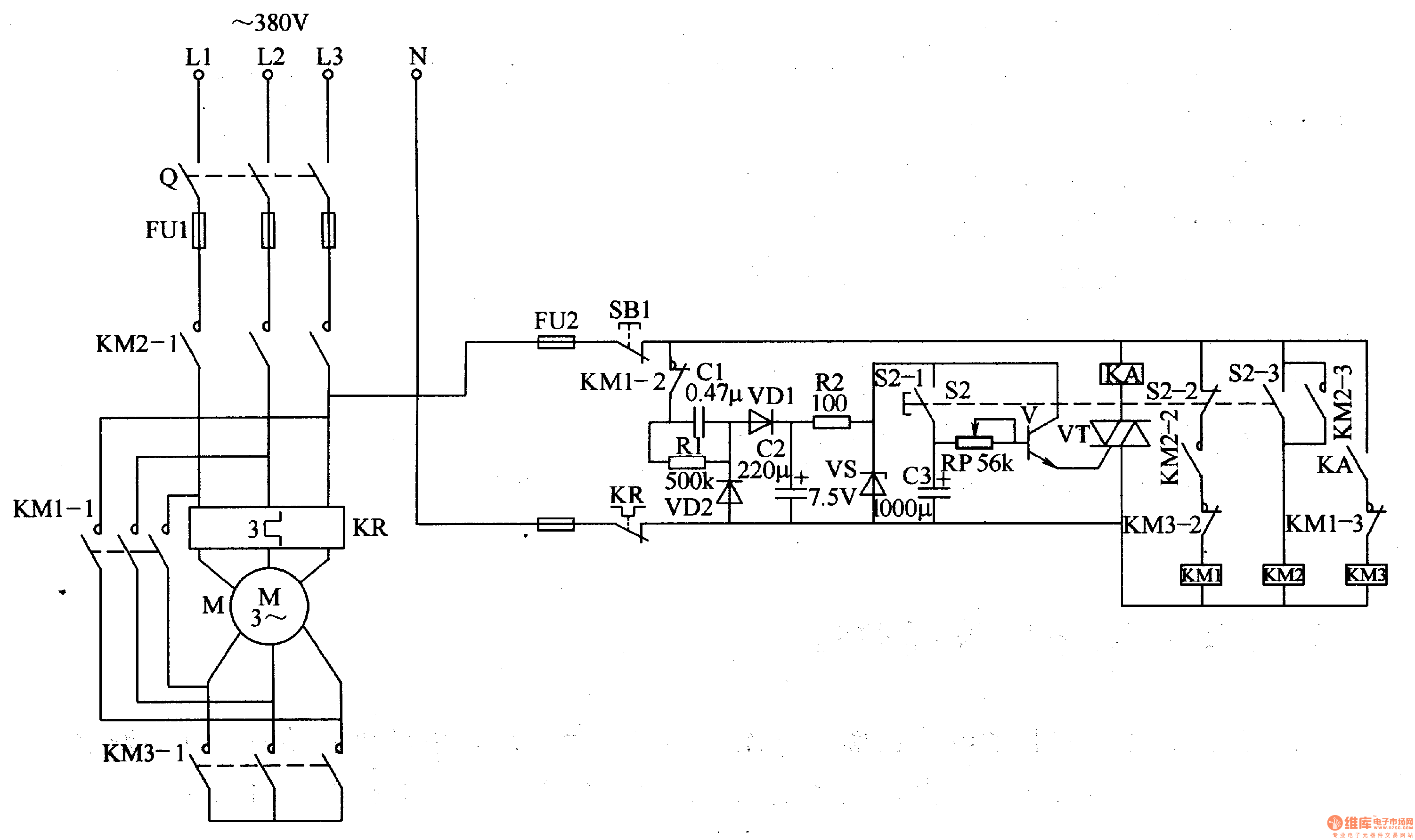
The motor voltage reducing starter circuit is composed of regulated power supply circuit, delay control circuit and control implement circuit, it is shown in the figure 8-56.
The regulated power supply circuit is made of fuses FU1, FU2, stop button S1, capacitors C1, C2, heat relay KR's normally closed contact, resistors R1, R2 and steady voltage diode VS.
The delay control circuit consists of starter control button S2 (S2-1-S2-3), capacitor C3, potentiometer RP, transistor V, TRIAC VT and intermediate relay KA.
When stop button S1 is pressed, the whole circuit is power failure and it stops working.
Reprinted Url Of This Article:
http://www.seekic.com/circuit_diagram/Control_Circuit/Motor_voltage_reducing_starter_2.html
Print this Page | Comments | Reading(3)

Article Categories
power supply circuit
Amplifier Circuit
Basic Circuit
LED and Light Circuit
Sensor Circuit
Signal Processing
Electrical Equipment Circuit
Control Circuit
Remote Control Circuit
A/D-D/A Converter Circuit
Audio Circuit
Measuring and Test Circuit
Communication Circuit
Computer-Related Circuit
555 Circuit
Automotive Circuit
Repairing Circuit
Code: