Basic Circuit
Motor brake
Published:2011/7/1 1:38:00 Author:Nicole | Keyword: motor, brake | From:SeekIC

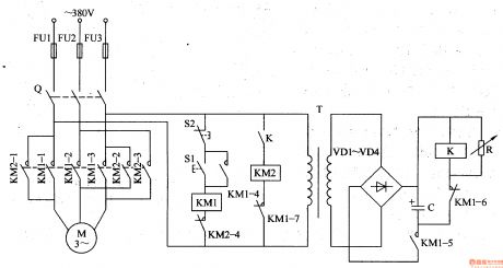
The motor brake circuit is composed of power transformer T, rectifier diode VD1-VM, changeable resistor R, capacitor C, relay K, AC contactor KM1, KM2 and starter button S1, stop button S2, it is shown in the figure 8-65.
After the starter button S1 is pressed, AC contactor KM1 works, the normally open contact KM1-1-KM1-5 is turned on, the normally closed contact KM1-6-KM1-7 is turned off, motor M runs, the power transformer T works too, after the induced voltage is rectified by VD1-VD4, it charges to capacitor C.
Reprinted Url Of This Article:
http://www.seekic.com/circuit_diagram/Basic_Circuit/Motor_brake.html
Print this Page | Comments | Reading(3)

Article Categories
power supply circuit
Amplifier Circuit
Basic Circuit
LED and Light Circuit
Sensor Circuit
Signal Processing
Electrical Equipment Circuit
Control Circuit
Remote Control Circuit
A/D-D/A Converter Circuit
Audio Circuit
Measuring and Test Circuit
Communication Circuit
Computer-Related Circuit
555 Circuit
Automotive Circuit
Repairing Circuit
Code: