Basic Circuit
Transfusion warmer 1
Published:2011/6/27 1:42:00 Author:Nicole | Keyword: Transfusion warmer | From:SeekIC

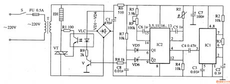
This transfusion warmer circuit is composed of astable multivibrator, temperature detector control circuit, heating circuit and power supply, it is shown in the figure 9-151.
The astable multivibrator is made of resistors R2, R3, capacitors C2, C3 and time base integrated circuit IC1.
The temperature detector control circuit consists of trigger integrated circuit IC2, thermal resistor RT, potentiometer RP, resistors R4, R5, R7-R9, capacitors C4-C6, transistor V and diodes VD5, VD6.
The heating circuit is composed of light clutch VLC, resistor R1, thyristor VT and heater EH.
Reprinted Url Of This Article:
http://www.seekic.com/circuit_diagram/Basic_Circuit/Transfusion_warmer_1.html
Print this Page | Comments | Reading(3)

Article Categories
power supply circuit
Amplifier Circuit
Basic Circuit
LED and Light Circuit
Sensor Circuit
Signal Processing
Electrical Equipment Circuit
Control Circuit
Remote Control Circuit
A/D-D/A Converter Circuit
Audio Circuit
Measuring and Test Circuit
Communication Circuit
Computer-Related Circuit
555 Circuit
Automotive Circuit
Repairing Circuit
Code: