Basic Circuit
Electronic snore-ceasing equipment 4
Published:2011/6/27 4:15:00 Author:Nicole | Keyword: Electronic snore-ceasing equipment | From:SeekIC

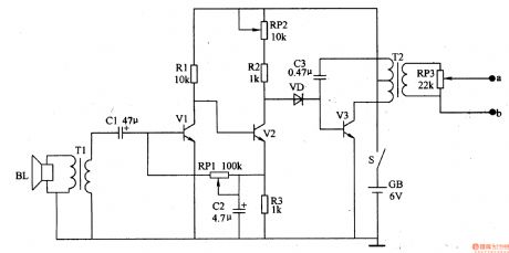
This snoring detection amplifier circuit is composed of loudspeaker BL, coupling transformer T1, capacitors C1, C2, audio amplifier transistors V1, V2, resistors R1-R3 and potentiometers RP1, RP2.
The pulse oscillator is made of diode VD, oscillation tube V3, capacitor C3, pulse transformer T2 and potentiometer RP3.
After the power supply switch S is connected, the snoring detection amplifier circuit starts to work. When there is no snoring, V2's collector has no audio voltage output, V3 is in off state, the electrodes a,b has no stimulation pulse output.
Reprinted Url Of This Article:
http://www.seekic.com/circuit_diagram/Basic_Circuit/Electronic_snore_ceasing_equipment_4.html
Print this Page | Comments | Reading(3)

Article Categories
power supply circuit
Amplifier Circuit
Basic Circuit
LED and Light Circuit
Sensor Circuit
Signal Processing
Electrical Equipment Circuit
Control Circuit
Remote Control Circuit
A/D-D/A Converter Circuit
Audio Circuit
Measuring and Test Circuit
Communication Circuit
Computer-Related Circuit
555 Circuit
Automotive Circuit
Repairing Circuit
Code: