
Circuit Diagram
Index 1172
Accelerometer_digitizer_piezoelectric
Published:2009/7/24 3:21:00 Author:Jessie
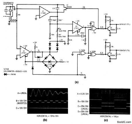
Fig. 14-1 This circuit is essentially a current-to-frequency converter that responds to ac input developed by an accelerometer, As shown In Fig. 14-1B, the piezoelectric accelerometer produces a damped sine-wave when subjected to acceleration (Trace A). This signal is converted to a signal output (Trace B), which keeps track of acceleration polarity. The frequency output (Trace C)supplies amplitude data. Note the drop In output frequency as the accelerometer wave-form damps. To trim, apply a known amplitude acceleration to the transducer and adjust the gain trim for the correct output frequency, Notice that the transducer manufacturer'datasheet shows means of simulating acceleration electrically, and it includes the necessary scale factors, Linear Technologv Linear Applications Handbook 1990 p AN-15,-16. (View)
View full Circuit Diagram | Comments | Reading(1719)
STEREO_HEADPHONE_AMPLIFIER
Published:2009/7/24 3:21:00 Author:Jessie
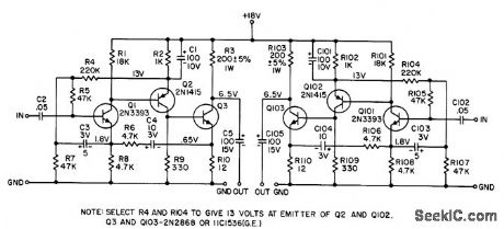
Will drive dyanamic headphones of 75 to 400 ohms impedance to power level of 60 mw. Program source may be tuner or ceramic car tridge. Frequency response is fiat within 0.33 db from 20 cps to 20 kc. High input impedance, 1 meg up to 2.5 kc and decreasing to 400K at 15 kc, is obtained by using bootstrapped bias network for Q1 along with negative feedback.- Transistor Manual, Seventh Edition, General Electric Co., 1964, p 272. (View)
View full Circuit Diagram | Comments | Reading(695)
12_V_preset_output_controller_with_power_monitor
Published:2009/7/24 3:21:00 Author:Jessie

Figure 7-72 shows a MAX773 connected to provide 12-V output. with a power-monitor(or low battery )function.See Fig,7-68 for component suppliers. MAXIMNEW RELEASES DATA Book, 1995, P.4-151. (View)
View full Circuit Diagram | Comments | Reading(640)
STEREO_MULTIPLEX_PHASE_MODULATOR
Published:2009/7/24 3:19:00 Author:Jessie
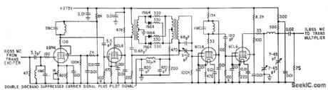
Circuit serves for frequency-modulating main terrier signal by stereophonic subcarrier in four-diode ring modulator to which 19-kc pilot subcarrier is also applied. Resultant signal is phase-modulated at same 11.055-Mc carrier frequency as input signal.-Modifying and F-M Transmitter for Compatible Stereo Multiplex, Electronics, 34:28, p 60-62. (View)
View full Circuit Diagram | Comments | Reading(1314)
Two_cell_voltmeter_with_high_input_resistance
Published:2009/7/24 3:18:00 Author:Jessie

This two-cell voltmeter has an input resistance in excess of 1,000,000 MΩ. Full-scale deflection is ±500 mV, ±150 mV, and ±15 mV. Higher voltage ranges can be added with external input-voltage attenuator networks. The meter is in series with the gain network, thus eliminating the meter temperature-coefficient error term. Standby supply current (meter not deflected) is 300 μA. At full-scale deflection, current rises to 800 μA. Carbon-zinc battery life should be in excess of 1000 hours. (View)
View full Circuit Diagram | Comments | Reading(547)
400_MHz_125_W_push_pull_amplifier
Published:2009/7/24 3:18:00 Author:Jessie
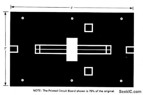
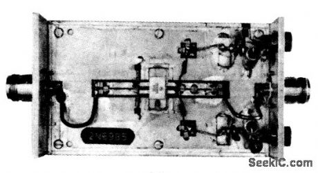
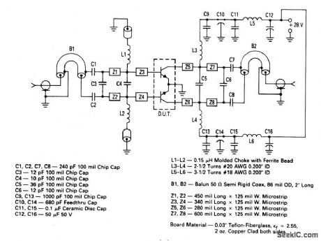
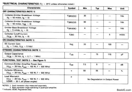
The electrical characteristics for the 2N6985 (push-pull transistor ) shown in this circuit are given in Fig .2-41B. Figures 2-41C and 2-41D show the photomaster ,and parts location , respctively, Those not familiar with microstrip techniques (for Z1 through Z5) should read the many Motorola publications, such as AN548A and AN555. (View)
View full Circuit Diagram | Comments | Reading(743)
Two_cell_picoammeter
Published:2009/7/24 3:18:00 Author:Jessie

This circuit covers the range from ±1.5 pA to ±500 μA. Higher current ranges are possible with suitable switching techniques and scaling resistors. The 1-MΩ input resistor provides input-transient protection. Higher current ranges require that this resistor be reduced. The 10-MΩ resistor at pin 2 decouples possible high input capacitance, and reduces the tendency for the circuit to oscillate. (View)
View full Circuit Diagram | Comments | Reading(1453)
DRIVER
Published:2009/7/24 3:18:00 Author:Jessie
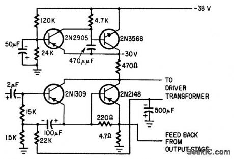
Upper pair of transistors provides voltage regulation, filtering, turn-on time delay, and decoupling for audio driver transistors below.-S. Messin and T. E. Nawalinski, A Solid Stale Stereo Set Built in Modules, Electronics, 38:16, p 88-92. (View)
View full Circuit Diagram | Comments | Reading(971)
_55_to__125℃_thermometer_using_silicon_sensors
Published:2009/7/24 3:17:00 Author:Jessie

Fig. 13-46 This circuit shows a simple connection between an LTC1092 and industry-standard 1 μA/°K current-output sensors. Resolution is 0.25℃ and accuracy is limited by the sensor and resistors. Standard 10-mV/°K voltage-output sensors can also be connected directly to the LTC1092 input in a similar manner. Linear Technology. Linear Applications Handbook 1990 p DN5-2。 (View)
View full Circuit Diagram | Comments | Reading(547)
9_V_high_efficiency_controller_lower_power
Published:2009/7/24 3:17:00 Author:Jessie

Figure 7-71 shows the MAX770/71/72 connected to provide 9-V output with a 4-V input. See Fig. 7-68 for component suppliers. These IC controllers are similar to the MAX1771 (Fig. 7-53), but with lower power capability. MAXIM NEW RELEASES DATA BOOk, 1995, P. 4-150. (View)
View full Circuit Diagram | Comments | Reading(555)
10_Hz_TO_10_kHz_VOLTAGE_CONTROLLED_OSCILLATOR
Published:2009/7/1 20:47:00 Author:May

View full Circuit Diagram | Comments | Reading(730)
TWO_INPUT_RED_GREEN_LED
Published:2009/7/1 20:47:00 Author:May

Uses Monsanto MV5491 having red and green LEDs in same housing, connected inversely in parallel so current in one direction gives green and reverse current gives red. Two different drivers are used, SN75452 noninverting and SN75451 inverting. Each LED pair shows one color for correct polarity at its driver input and other color for opposite polarity.-K. Powell, Novel Indicator Circuit, Ham Radio, April 1977, p 60-63. (View)
View full Circuit Diagram | Comments | Reading(1643)
LINEAR_VOLTAGE_CONTROLLED_OSCILLATOR
Published:2009/7/1 20:46:00 Author:May

The linearity of input sweepvoltage versusoutput frequency is significantlyimproved by using an op amp. (View)
View full Circuit Diagram | Comments | Reading(0)
COMPACTRON_FOR_STEREO
Published:2009/7/24 3:17:00 Author:Jessie
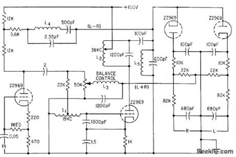
Z2969 compactron performs functions of two triodes and two diodes in circuit for adapting f-m receivers to stereo.-L. Dillon, Single Compactron Adapts Receiver for Stereo, Electronics, 34:43, p 62-64. (View)
View full Circuit Diagram | Comments | Reading(620)
VOLTAGE_LEVEL_DETECTOR
Published:2009/7/1 20:44:00 Author:May

View full Circuit Diagram | Comments | Reading(687)
PULSE_SEQUENCE_DETECTOR
Published:2009/7/1 20:42:00 Author:May

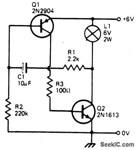
The resistor divider connected between Q1and Q2 supplies IH to Q1 after input A triggersit. It also prevents input B from triggering Q2until Q1 conducts. Consequently, the first Binput pulse after input A is applied will supply current to RL. (View)
View full Circuit Diagram | Comments | Reading(0)
F_V_WITH_4151
Published:2009/7/1 20:41:00 Author:May

1Uses Raytheon 4151 as frequency-to-voltage converter for generating currentpulses having precise amplitude and width.Average value of output pulse train is directly proportional to input frequency. Article gives design equations. Response time can be improved and ripple reduced by using secondorder (double-pole) low-pass filter as shown in diagram (b). Ripple is Iess than 0.1 V P-P over range of 10 to 10,000Hz when R1 and R2 are 100K and C1 and C2 are 0.1 μF.-T. Cate, IC V/F Converters Readily Handle Other Functions Such as F/ V,A/D, EDN Magazine, Jan. 5, 1977, p 82-86. (View)
View full Circuit Diagram | Comments | Reading(855)
TREMOLO_AMPLlFIER
Published:2009/7/1 20:40:00 Author:May
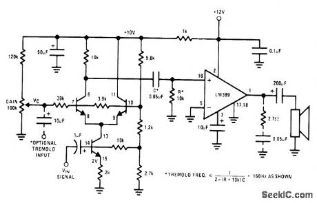
Provides amplitude modulation at subaudio rate (usually between 5 and 15 Hz) of audio-frequency input signal. Uses National LM389 attay having three transistors along with power amptifier. Transistors form differential pair having active currentsource tail to give output proportional to product of two input signals. Gain control pot is adjusted for desired tremolo depth. Interstage RC network forms 1 60-Hz high-pass filter, requMng that tremolo frequency be tess than 160 Hz.- Audio Handbook, National Semiconductor, Santa Clara, CA, 1977, p 4-33-4-37. (View)
View full Circuit Diagram | Comments | Reading(606)
TANGENTIAL_WAVEFORM_GENERATOR
Published:2009/7/24 3:38:00 Author:Jessie
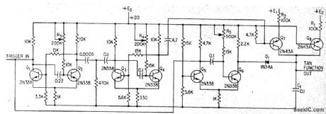


Generates approximation of tangent function for slant-range correction of video signal fromairborne infrared scanner. Ramp mvbr Q5-Q6 and timing mvbr Q1-Q2 are triggered simultaneously.-J. L. Woika, Generating Tangential Sweeps for Infrared Mapping, Electronics, 34:41, p 64-66. (View)
View full Circuit Diagram | Comments | Reading(550)
WINDICATOR
Published:2009/7/1 20:37:00 Author:May
Circuit Notes
Two TTL ICs and a handful of other com-ponents are all that is needed for a circuit that will indicate which of four buttons was pressed first, as well as lock out all other entries. A logic 0 at one of the Q outputs, lights the ap; propriate LED and locks out other entries by taking the clock input low. (View)
View full Circuit Diagram | Comments | Reading(539)
| Pages:1172/2234 At 2011611162116311641165116611671168116911701171117211731174117511761177117811791180Under 20 |
Circuit Categories
power supply circuit
Amplifier Circuit
Basic Circuit
LED and Light Circuit
Sensor Circuit
Signal Processing
Electrical Equipment Circuit
Control Circuit
Remote Control Circuit
A/D-D/A Converter Circuit
Audio Circuit
Measuring and Test Circuit
Communication Circuit
Computer-Related Circuit
555 Circuit
Automotive Circuit
Repairing Circuit