
Circuit Diagram
Index 1164
AF_METER_
Published:2009/7/1 22:32:00 Author:May

Timer IC1 forms basis for Iinearfrequency meter covering audio spectrum. Mono MVBR puts out fixed-width pulse when triggered by unknown inputfrequency. Article covers operation and calibration. Errata: pin 4 of 555 should be connected to pin 8 instead of to pin 2,-G.Hinkle,IC Audio IC Audio Frequency Meter,73 Magazine,Holiday issue 1976、p 61. (View)
View full Circuit Diagram | Comments | Reading(811)
TWO_SECTION_STAIRCASE
Published:2009/7/24 3:07:00 Author:Jessie
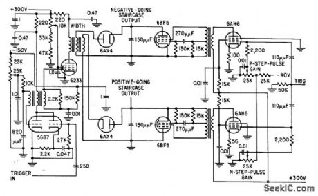
Negative-going staircase is developed from positive potential, and positive-going staircase from negative potential. Output voltage across 150-mmfd capacitors is 800V peak-to-peak, enough to drive crt directly.-M. T. Nadir, Microsecond Sampler Handles 126 Channels, Electronics, 32:4, p 36-39. (View)
View full Circuit Diagram | Comments | Reading(562)
NANOSECOND_PULSE_DETECTOR
Published:2009/7/1 22:31:00 Author:May

Used to provide visual indication of presence of a nonrepetitive digital pulse having microsecond or nanosecond width. Bistable IC transfers pulse information from its data input to the Q output on positive-going edge of clock pulse, to energize LED indicator.-P. V. Prior, Digital Pulse Detector, Wireless World, March 1976, p 90. (View)
View full Circuit Diagram | Comments | Reading(1011)
REVERBERATION
Published:2009/7/1 22:30:00 Author:May

Used in sound synthesizer developed for generating wide variety of musical and other sounds. Four-transistor driver feeds spring-type reverberation unit at up to about 4 kHz, with switch giving choice of reverberation only or reverberation combined with input signal at VA. Amount of reverberation can be controlled manually with R3 or automatically with voltage-controlled amplifier or voltagecontrolled filter of synthesizer. Three-part article gives all circuits and describes operation in detaiL-T. 0rr and D. W. Thomas, Electronic Sound Synthesizer, Wireless World, Part 2-Sept. 1973, p 429-434 (Part 1-Aug. 1973, p 366-372; Part 3-Oct. 1973, p 485-490). (View)
View full Circuit Diagram | Comments | Reading(1088)
LIGHT_SENSITIVE_THEREMIN
Published:2009/7/1 22:23:00 Author:May

Tone of loudspeaker increases and decreases in frequency as flashlight is moved in vicinity of photocell in darkened room, Use Radio Shaok 276-116cadmium sulfide photocell. Cell resistance decreases with light, increasing frequency ot audio oscillator. Continuously changing frequency resembles that produced by hand-con-ttolled theremin.-F. M, Mims, Electronic Music Projects, Vol. l, 'Radio Shack, Fort Worth. TX. 1977. 2nd Ed., p 91-95. (View)
View full Circuit Diagram | Comments | Reading(1774)
Thermocouple_cold_junction_compensation_grounded_thermocouple
Published:2009/7/24 3:06:00 Author:Jessie

Fig.13-39 This circuit is preferable to that of Fig.13-38, but it requires dualsupplies. To trim, short out the LM329B and adjust R5 so that VO(across R1)equals the Seebeck coefficient(in μV/℃)times the absolute temperature. Remove the short and adjust R4 so that VO, equals the thermocouple output voltage at ambient. This circuit requires good grounding because any ground differential will appear in series with the thermocouple output, National Semiconductor Linear Applications Handbook, 1991, p. 524. (View)
View full Circuit Diagram | Comments | Reading(1321)
FREQUENCY_METER_
Published:2009/7/1 22:21:00 Author:May

High- precision frequency-to-voltage converter can be used as frequency meter in laboratory. Input frequency range up to 1 kHz is converted to corresponding full-scale voltage value of +5 V. Two-pole filter removes ripple from positive output pulses across R1 before signal is fed to 3130 opamp that provides gain and zero adjustments.-W. G. Jung,″IC Timer Cookbook,″Howard W .Sams,Indianaplis,IN,1977,p 192-186. (View)
View full Circuit Diagram | Comments | Reading(1190)
ENLARGER_TIMER_STEP_CIRCUIT_0_TO_59_s
Published:2009/7/24 3:06:00 Author:Jessie


This circuit shows how to set up a NE555 timer to produce timing steps from 0 to 59 s in 1-s intervals. (View)
View full Circuit Diagram | Comments | Reading(659)
CLICKING_METRONOME
Published:2009/7/1 22:19:00 Author:May

Basic lamp-flashing circuit iS used to produce sharp click In loudspeaker each time Q2 is turned on by RC oscillator Q1 R2 adjusts repetition rate over range of 20-280 beats per minute Changing value of C1 varies tone of clicks.-F M Mims.″Transistor Projects,vol.1. Radio Shack.Fort Worth.TX.1977.2nd Ed,p 33-39. (View)
View full Circuit Diagram | Comments | Reading(829)
Single_cell_microphone_amplifier
Published:2009/7/24 3:06:00 Author:Jessie
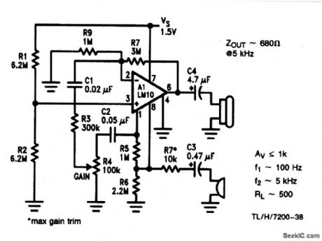
As shown, the circuit provides a voltage-gain of 60 dB over a 5-kHz bandwidth, loaded at 500 Ω. Unloaded, it is possible to get 60-dB gain up to 10 kHz. Input impedance is 10 kΩ. Notice that with a single cell, the output cannot swing much below 150 mV, nor closer than 800 mV to the supply. Input noise is 40 to 50 nV/√Hz (about equal to the op amp). (View)
View full Circuit Diagram | Comments | Reading(531)
LED_BAR_GRAPH_DRIVER
Published:2009/7/1 22:18:00 Author:May

The circuit uses CA3290 BiMOS dual voltage comparators. Non-inverting inputs of A1and A2 are tied to voltage divider reference.The input signal is applied to the inverting inputs. LEDs are turned on wheninput voltage the reaches the voltage on the reference divider. (View)
View full Circuit Diagram | Comments | Reading(941)
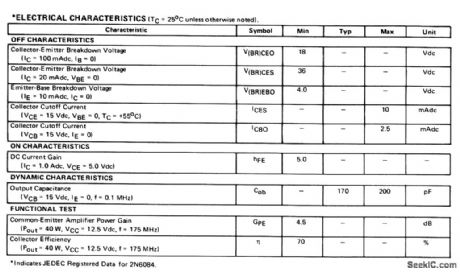
400_MHz_60_W_amplifier_28_V_supply
Published:2009/7/24 3:06:00 Author:Jessie
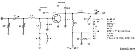
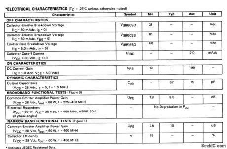
The electrical characteristics for the 2N6439 shown in this circuit are given in Fig.2-39B. (View)
View full Circuit Diagram | Comments | Reading(552)
LOW_COST_BAR_GRAPH_INDICATOR_FOR_AC_SIGNALS
Published:2009/7/1 22:15:00 Author:May

Indicator was designed for displaying the peak level of small ac signals from a vanety of transducers including microphones,stram gauges and photodiodes.The circuitresponds to input signals contained within the audio frequency spectrum, i.e.,30 Hz to 20 kHz,although a reduced response extends up to 40 kHz.Maximum sensitivityfor the component values shown,with VR1 fully clockwise,IS 30 mV peak-to-peak.The indicator can be calibrated by setting VR1 when an appropriate input signal is applied. (View)
View full Circuit Diagram | Comments | Reading(797)
VOLTAGE_CONTROLLED_AMPLIFIER
Published:2009/7/1 22:12:00 Author:May
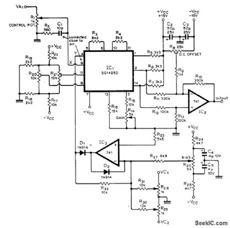

Gain is linearly controlled by sum of input control voltages and a bias voltage, to provide amplitude modulation as required for synthesizer used to generate wide variety of sounds. Heart of circuit is linear four-quadrant multiplier IC. Output is taken between two load resistors, with differential amplifier IC2 removing common-mode signal Article describes operation In detail and glves all other circuits of synthesizer.along with procedure for aligning preset controls R8、R14.R20.and R21,-T Orr and D VV Thomas、ElectroniC Sound Synthesizer、Wireless World.、Part2-Sept .1973、p429-434(Part 1-Aug 1973.p366-372;Part 3-Oct 1973.p485-490) (View)
View full Circuit Diagram | Comments | Reading(0)
64_STEPS
Published:2009/7/24 3:04:00 Author:Jessie
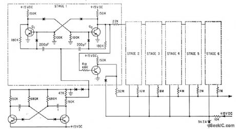
R-C dock, six binary counters, and summing network give repetitive staircase waveform having 64 equally spaced potential steps between and including minimum and maximum voltages. Free-running astable mvbr (lower left) generates 40-cps dock signal. Transistors can be 2N697.-E. E. Eberhard, Latest Thin-Film Circuit Techniques, Electronics, 35:24, p 37-39. (View)
View full Circuit Diagram | Comments | Reading(525)
TACHOMETER_WITCH_SOUARE_WAVE_OUT_PUT
Published:2009/7/1 22:11:00 Author:May

National LM2907 tachometerIC providessquare-wave output at same frequency as sine wave generated by magnetic pickup,for use asline driver in automatic control system.-″Linear Applications,vol .2, National Semiconductor、Santa Clara、CA、1976,AN-162,p12-13. (View)
View full Circuit Diagram | Comments | Reading(1027)
MULTIPLEXING_7_DIGITS
Published:2009/7/1 22:10:00 Author:May

Uses Motorola MC3490 anode driver for active-high inputs (MC3494 for active-Iow inputs) to accept digitselect signals from multiplex logic source and drive display anodes directly. Constant cathode currents are maintained for gas-discharge display by Bionics Dl-300 IC, to provide constant brightness without using supply-voltage reguIation. For each digit added to display, equal number of anode drivers is required. Only one cathode driver is needed because all cathodes are bused together.-D. Sien, Multiplex Display Circuit Features Minimum Parts Count, EDN Magazine, May 5,1977, p 112. (View)
View full Circuit Diagram | Comments | Reading(618)
5_min_SHUTOFF
Published:2009/7/1 22:10:00 Author:May

Vehicleintrusion alarm shuts off automatically in about 5 min after being triggered, as required by law in some states. Drain on battery is negligible until alarm is set off by intruder. Once triggered, operation sequence is not affected by subsequent opening or closing of doors. System uses two CMOS CD4001AE quad two-input NOR gates for switching logic. IC1 provides sensor interface, latch, and entry/exit time delays. IC2 provides output through Q1 amd relay, as well as automatic shutoff delay. Article gives construction details and layout for printed-circuit board.-W. J. Prudhomme, Vehide Security Systems, 73 Magazine, Oct. 1977, p 122-125. (View)
View full Circuit Diagram | Comments | Reading(490)
175_MHz_40_W_amplifier_125_V_supply
Published:2009/7/24 3:01:00 Author:Jessie
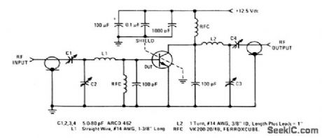
The electrical characteristics for the 2N6083 shown in this circuit are given in Fig.2-37B. (View)
View full Circuit Diagram | Comments | Reading(700)
High_temperature_thermometer_with_analog_and_digital_outputs
Published:2009/7/24 3:01:00 Author:Jessie

Fig. 13-36 In this circuit, an LF347 is used to signal condition a platinum RTD and provide simultaneous analog and frequency outputs. These outputs are accurate to ±1℃ over a range of300 to 600℃ (572 to 1112°F). Although the circuit maintains linearity over a much wider range, the nonlinear response of the RTD mover wide range is the limiting factor, as shown in the graph of Fig. 13-36B. To calibrate the thermometer, substitute a high-quality decade box (General Radio 1432-KL) for the sensor. Alternately adjust the zero (300℃) and full-scale (600℃) potentiometers for the resistance values noted in Fig. 13-36B until the A2 output is calibrated (3 to 6 V). Then, adjust the 200-kΩ frequency trim so that the output frequency corresponds to the value at the A2 output (300 Hz at the frequency output for 3 V at the analog output). National Semiconductor, Linear Applications Handbook 1991,p. 729.730. (View)
View full Circuit Diagram | Comments | Reading(1487)
| Pages:1164/2234 At 2011611162116311641165116611671168116911701171117211731174117511761177117811791180Under 20 |
Circuit Categories
power supply circuit
Amplifier Circuit
Basic Circuit
LED and Light Circuit
Sensor Circuit
Signal Processing
Electrical Equipment Circuit
Control Circuit
Remote Control Circuit
A/D-D/A Converter Circuit
Audio Circuit
Measuring and Test Circuit
Communication Circuit
Computer-Related Circuit
555 Circuit
Automotive Circuit
Repairing Circuit