
Circuit Diagram
Index 1165
Single_cell_meter_amplifier
Published:2009/7/24 3:01:00 Author:Jessie

Accuracy for this meter amplifier can be maintained over a 15°C to 55°C range for a full-scale sensitivity of 10 mV to 100 mA. Offset-voltage error is nulled with R5, and bias current is balanced out with R4. Both offset and bias are operated from the reference, and are generally unaffected by changes in battery voltage, so frequency adjustments should not be necessary. Total current drain is under 0.5 mA, giving an approximate life of 3 to 6 months with an AA cell, or over one year with a D cell. (View)
View full Circuit Diagram | Comments | Reading(560)
STAIRCASE_GENERATOR
Published:2009/7/24 3:01:00 Author:Jessie
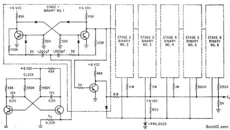
Major modification of conventional 64step voltage staircase generator for integrated-circuit construction involved dropping supply voltage from 15 V to 0 V, To cut power drain in half and reduce summing resistor network values. Circuit uses Pacific Semiconductor PD101 microdiodes and uncased Fairchild ESP-42-1 transistors.-E. E. Eberhard, Latest Thin-Film Circuit Techniques, Electronics, 35:24, p 37-39. (View)
View full Circuit Diagram | Comments | Reading(0)
SAMPLING_STAIRCASE
Published:2009/7/24 3:00:00 Author:Jessie
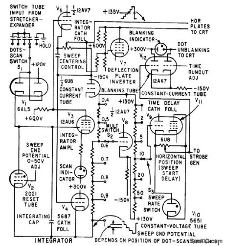
Provides horizontal def action voltage for crt and time advance information for comparator tube in strobe generator. Increase of d-c bias superimposed on staircase advances start of sampling with respect to start of ramp, decreasing op parent lime delay in start of d-c trace. Blanking indicator in staircase generator is on when screen is blanked. Scan indicator lashes when staircase is sweeping. Staircase advances one stop for each displayed sample.-W. E. Bushor, Sample Method Displays Millimicrosecond Pulses, Electronics, 32:31, p 69-71. (View)
View full Circuit Diagram | Comments | Reading(639)
175_MHz_30_W_amplifier_125_V_supply
Published:2009/7/24 3:00:00 Author:Jessie

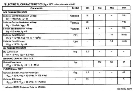
The electrical characteristics for the 2N6083 shown in this circuit are given in Fig.2-36B. (View)
View full Circuit Diagram | Comments | Reading(1742)
EXPANDED_SCALE_METER_DOT_OR_BAR
Published:2009/7/1 22:09:00 Author:May

A bar graph driver IC LM314 drives an LED display.The LEDs may be separateor in a combined (integral) bar graph display. (View)
View full Circuit Diagram | Comments | Reading(3683)
VISUAL_INDICATOR
Published:2009/7/1 22:08:00 Author:May

When circuit is activated by high output of burglar alarm circuit, 555 timer operating as very low frequency MVBR makes LED1 flash on and off during alarm condition. Alternate connection of LED1 to V+ holds LED1 on for standby while flashing it during alarm. Oscillator output is also available for other uses if desired. indicator can be located remotely from alarm.-W. G. Jung, IC Timer Cookbook, Howard W. Sams, Indianapolis, IN, 1977, p 232-235. (View)
View full Circuit Diagram | Comments | Reading(911)
BCD_DECODER_2
Published:2009/7/1 22:08:00 Author:May

Drive for 7-segment commonanode digital display is provided by RS7447 BCD to 7-segment decoder. Binary input indicator using RS7404 hex inverter and four LEDs shows input in binary form for decimal digits 0-9. Developed for classroom demonstrations. Red LEDs can be Radio Shack 276-805,and display is 276-053,F.M.Mims, Integrated Circuit Projects,vol.6, Radio Shack,Fort Worth,TX,1977,p 42-52. (View)
View full Circuit Diagram | Comments | Reading(4705)
HOTEL_ROOM_ALARM
Published:2009/7/1 22:07:00 Author:May

Alarm mounted in flashlight-shaped cylinder is positioned on floor inside hotel room in such a way that it is knocked over by intruder opening door. Mercury switch S2 then triggers SCR and activates Mallory SC-628P pulsed Sonalert alarm. Circuit latches on and can be tumed off only by use of Darlington-amplifier touch switch. Connection from base of Darlington to positive terminal of battery must be made through fingertips as shown by dashed line in orderto silence alarm. Once silenced, S1 can be opened to disconnect latch so alarm can be moved. Other applications include protection of unattended luggage. C1 is 0.1 μF, R1 is 1 megohm, R2 is 1K, R3 is 39K, and S2 is mercury element removed from GE mercury toggle switch,-R. F. Graf and G. J. Whalen, The Build-It Book of Safety Electronics, Howard W. Sams, Indianapolis, IN, 1976, p 19-24. (View)
View full Circuit Diagram | Comments | Reading(1334)
VACUUM_FLUORESCENT_DISPLAY
Published:2009/7/1 22:06:00 Author:May

This circuit uses the CA3207 sequence driver and CA3208 segment latch-driver in combination to drive display devices of up to 14 segments with up to 14 characters of display. The CA3207 selects the digit or character to be displayed in sequence, CA3208 turns on the required alphanumeric segments. (View)
View full Circuit Diagram | Comments | Reading(1129)
PENDULUM_DISPLAY
Published:2009/7/1 22:05:00 Author:May

Ten series rows of LEDs or Christmas-tree Iights mounted behind diffused plastic are energized sequentially left to right,then right to left by counter-driven drivers to create illusion of bwinging pendulum. Circuit includes provision for pause at each change of direction, as in actual pendulum of clock. Article aces operation ol circuit in detail.-E. A. Flynn, Put a Pendulum in Your Electronic Grandfather Clock, EDN Magazine, May 5, 1975, p 88 and 90. (View)
View full Circuit Diagram | Comments | Reading(1697)
LITTLE_DIPPER
Published:2009/7/1 22:03:00 Author:May

The circuit consists of two basic circuits, the oscillator and the detector. The oscillator uses an FET in a Colpitts configuration. The energy circulating in the oscillator tank is coupled through C4 to the detector circuit, where a small diode (D2) rectifies it, feeding a dc voltage to the Darlington pair (Q2, A3) con-trolled by the sensitivity control (R3). Any smallvariations in the bias of the amplifier will cause large variations of current through the LED indicator in the DiP mode; however, in the PEAK mode the current produces a corre-sponding voltage ropthrough R5 and the action of the LED is reversed. The circuit shown will work practically on any frequency from LF to VHF if the appropriate components are used. (View)
View full Circuit Diagram | Comments | Reading(820)
MULTIPLEXED_BRIGHTNESS_CONTROL
Published:2009/7/1 22:03:00 Author:May


Developed for use with single-chip digital clocks in which several displays are multiplexed. Provides automatic brightness control by using variable duty cycle and switching it on and off in synchronism with display of time. Uses 555 timer in monostable mode, triggered by multiplex oscillator to determine off time of display.When ambient light is bright, resistance of ORP12 photocell is low and display is on most of time. Set 470K pot to give low light output without mistriggering under dark conditions.Timer can also drive decimal point directly and give matched brightness.-M. G. Martin, Automatic Display-Brightness Control, Wireless World, April 1976, p 61. (View)
View full Circuit Diagram | Comments | Reading(660)
HI_L0_LED_FREQUENCY_DISPLAY
Published:2009/7/1 22:03:00 Author:May

Apparent rotation of flashing LEDs around square indicates whether input frequency is above or below reference frequency. Input and reference waveforms may have any shape, because Schmitt triggers reshape both to give rectangular pulses which flip-flops divide by two so outputs are square waves with mark-space ratios at half original frequency. Squarewaves are gated together to produce rectangular pulse train having mark-space ratio that depends on phase difference between the two square waves.Logic is arranged to drive LEDs at rotation rate of half the difference between input and referencefrequencies. Correct positioning of LEDs in square is shown on small diagram.Reference frequency input should be via BC108B (not shown), same as for input frequency.-C. Clapp, Beat-Frequency Indicator, Wireless World, Nov. 1976, p 63. (View)
View full Circuit Diagram | Comments | Reading(980)
NOISE_SOURCE
Published:2009/7/1 21:52:00 Author:May

Used in synthesizer for generating wide variety of musical and other sounds, to provide any combination of white, filtered, and VLF noise to be used directly as audio signal or as control signal. Source for white noise is Tr1, which is a germanium transistor selected for high leakage or heated enough to make it leaky, so as to produce an average noise level of about 40 mV P-P. Filtered (colored) noise is produced by driving spec-trum-shaping network (Baxandall tone control) with white noise. Preset control R17. is adjusted so output shows no clipping when both red and blue tone controls are at maximum. VLF noise is extracted from white noise by either of two low-pass filters selected by S1. Three-part article describes operation in detailand gives all other circuits used in synthesizer-T. Orr and D. W. Thomas, Electronic Sound Synthesizer, Wireless World, Part 3-Oct. 1973, p 485-490 (Part 1-Aug. 1973, p 366-372; Part 2-Sept. 1973, p 429-434). (View)
View full Circuit Diagram | Comments | Reading(968)
GRID_DIP_OSCILLATOR
Published:2009/7/1 21:52:00 Author:May

Millen 90652 solidstate grid-dip oscillator uses MOSFET operating in split-Colpitts circuit with resonating tank connected between drain and gate. Circuit is tuned by split-stator variable capacitor with rotorgrounded, chosen to cover 1.7 to 300 MHz with seven plug-in coils. Oscillator also functions as Q multiplier that increases sensitivity.RF voltage across tuned circuit is indicated by meter whose reading dips for resonance with coupled test circuit. Full-wave rectifier CR1-CR2 provides DC voltage for meter and some overload protection for MOSFET. Meter is suppressed-zero type, with readings only for upper portion of current range. J3 is provided for use with low-frequency coils.-W. M. Scherer,CQ Reviews: The Millen Model 90652 Solid-State Dipper, CQ, Sept. 1971, p 63-64, 66, and 96. (View)
View full Circuit Diagram | Comments | Reading(4712)
OCTAL_DISPLAY
Published:2009/7/1 21:47:00 Author:May

Circuit provides display of 8-bitdata word in conventional octal form forconvenience in experimentation with microprocessors and small computers. Three-state counter built around synchronously operated JK flip-flops provides digit and data selection. The two or threq bits appropriate to each display are steered to 7-segment decoder by wired-AND gates and inverters. Oscillator multiplexing frequency is about 2 kHz.-R. D. Mount, Octal Display for Microprocessors, Wireless World, March 1977, p 41. (View)
View full Circuit Diagram | Comments | Reading(2532)
WAVEFORM_GENERATOR_FOR_CURVE_TRACER
Published:2009/7/24 3:06:00 Author:Jessie
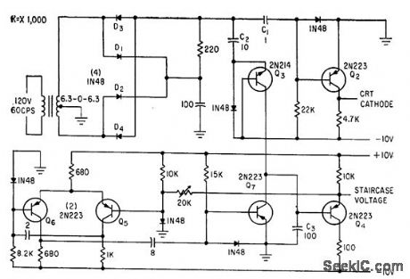
Generates blanking signal at collector of Q2 and staircase waveform at emitter of Q4 by charge transfer from C2 to C3.-C. J. Candy, Simplified Curve Tracer for Transistors and Diodes, Electronics, 33:34, p 68-70. (View)
View full Circuit Diagram | Comments | Reading(729)
FUZZ_CIRCUIT
Published:2009/7/1 21:44:00 Author:May

Two diodes in feedback path or LM324 opamp create musical-instrument effect known as fuzz by limiting output voltage swing to ±0.7 V. Resultant square wave contains chiefly odd harmonics, resembling sounds of clarinet. Fuzz depth pot controls level at which clipping begins, and fuzz intensity pot controls output level.- Audio Handbook, National Semiconductor. Santa Clara. CA. 1977. p 5-11. (View)
View full Circuit Diagram | Comments | Reading(2810)
SI_ABBREVIATION___DISPLAY
Published:2009/7/1 21:43:00 Author:May

Programmed Signetics 8223 256-bit PROM is used as alphameric display having five 7-segment digits connected to form alphameric simulation of abbreviations for second, millisecond, microsecond, hertz, kilohertz, and megahertz as SEC, SEC-3, SEC-6, H2, H2 3, H2 6. Binary counter U3, 4-16 line decoder, and 5-digit parallel-connected Hewlett.Packard display form simple multi-plexer that addresses memory U4 one word at a time. External 1000-Hz square-wave oscillator drives counter and sets scanning rate. Requires only one 5-V supply. Article gives truth table for memoryand circuit for programmer required to set it up.-J.W,Springer,Function/Units Indicator Using LED Displays,Ham Radlio, March 1977,p 58-63. (View)
View full Circuit Diagram | Comments | Reading(1866)
Thermocouple_cold_junction_compensation_single_supply
Published:2009/7/24 3:05:00 Author:Jessie

Pig. 13-38 In this single-supply circuit, R3 and R4 divide down the 10-mV/°K output of the LM335 to match the Seebeck coefficient of the thermocouple. The LM329B and associated voltage divider provide a voltage to buck out the 0℃ output of the LM335. To calibrate, adjust R1 so that V1 (across R4) equals the thermocouple Seebeck coefficient (in μV/℃) times the ambient temperature in degrees Kelvin (note that absolute zero in the Kelvin scale -273.18℃). Then, adjust R, so thatV1- V2 (across R6) is equal to the thermocouple output voltage at the known ambient temperature. Note that the term ∞ is used to determine R4 and R6 is the Seebeck coefficient for the type of thermocouple selected (types J, T, K, or S). National Semtconductor Linear Applications Handbook 1991 p 523. (View)
View full Circuit Diagram | Comments | Reading(1856)
| Pages:1165/2234 At 2011611162116311641165116611671168116911701171117211731174117511761177117811791180Under 20 |
Circuit Categories
power supply circuit
Amplifier Circuit
Basic Circuit
LED and Light Circuit
Sensor Circuit
Signal Processing
Electrical Equipment Circuit
Control Circuit
Remote Control Circuit
A/D-D/A Converter Circuit
Audio Circuit
Measuring and Test Circuit
Communication Circuit
Computer-Related Circuit
555 Circuit
Automotive Circuit
Repairing Circuit