Signal Processing
Accelerometer_digitizer_piezoelectric
Published:2009/7/24 3:21:00 Author:Jessie | From:SeekIC

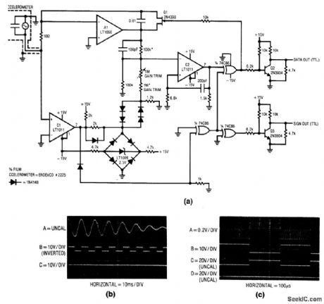
Fig. 14-1 This circuit is essentially a current-to-frequency converter that responds to ac input developed by an accelerometer, As shown In Fig. 14-1B, the piezoelectric accelerometer produces a damped sine-wave when subjected to acceleration (Trace A). This signal is converted to a signal output (Trace B), which keeps track of acceleration polarity. The frequency output (Trace C)supplies amplitude data. Note the drop In output frequency as the accelerometer wave-form damps. To trim, apply a known amplitude acceleration to the transducer and adjust the gain trim for the correct output frequency, Notice that the transducer manufacturer'datasheet shows means of simulating acceleration electrically, and it includes the necessary scale factors, Linear Technologv Linear Applications Handbook 1990 p AN-15,-16.
Reprinted Url Of This Article:
http://www.seekic.com/circuit_diagram/Signal_Processing/Accelerometer_digitizer_piezoelectric.html
Print this Page | Comments | Reading(3)

Article Categories
power supply circuit
Amplifier Circuit
Basic Circuit
LED and Light Circuit
Sensor Circuit
Signal Processing
Electrical Equipment Circuit
Control Circuit
Remote Control Circuit
A/D-D/A Converter Circuit
Audio Circuit
Measuring and Test Circuit
Communication Circuit
Computer-Related Circuit
555 Circuit
Automotive Circuit
Repairing Circuit
Code: