
Basic Circuit
Index 271
140_150_MHz_IN_5_kHz_STEPS
Published:2009/7/5 23:00:00 Author:May
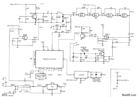
Developed for use with amateur 2-meter radios, to give direct choice of frequency by setting thumbwheel or lever switches. Phase.locked loop gives precise high-purity output. Input frequency to system is 4.5511 111-MHz reference signal from CD4060 crystal oscillator. Digital edge-triggered Hughes HCTR320 phase comparator maintains inputs of both frequency and phase coherence at lock; lock range is thus capture range, making locking on harmonics impossible. Article describes operation of circuit in detail, and gives construction details as well as circuit for keyboard entry system. Power supply is 723 precision regulator giving 7.15V.._M. I. Cohen, A Practical 2m Synthesizer, 73 Magazine, Sept, 1977, p 146-151. (View)
View full Circuit Diagram | Comments | Reading(1195)
LIGHT_PEN_WITH_INTERFACE
Published:2009/7/5 22:56:00 Author:May
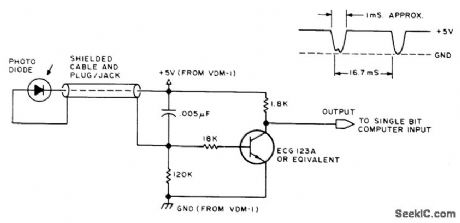
Any high-quality photodiode mounted in discarded housing of marking pen serves as pickup for holding against screen of video display. If diode is mounted in plastic lens, flatten end of lens with emery cloth to give narrower angle of acceptance. Developed for use with VDM-1 display terminal. Use CRO to monitor output as pen is moved across screen. Dark area on screen gives 5-VDC level, and white area gives dips. Article covers use in program design, editing memory dumps, and arranging complex displays.-J.Webster and J. Young, Add a $3 Light Pen to Your Video Display, BYTE, Feb, 1978, p 52, 54 56, and 58. (View)
View full Circuit Diagram | Comments | Reading(784)
3_V_STROBE
Published:2009/7/5 22:55:00 Author:May
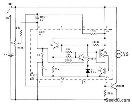
Flash rate of 1767 lamp can be adjusted from no flashes to continuously on, in circuit using National LM3909 flasher IC with extemal NPN power transistor rated at 1 A or higher. Can be used as variable-rate waming Iight, for advertising, or for spedal effects. With lamp in large reflector in dark room, flashes several times per second are almost fast enough to stop motion of dancer.-P. Lefferts, Power-Miser Flasher IC Has Many Novel Applications, EDN Magazine, March 20, 1976, p 59-66. (View)
View full Circuit Diagram | Comments | Reading(477)
1_Hz_LAMP_BLINKER
Published:2009/7/5 22:53:00 Author:May
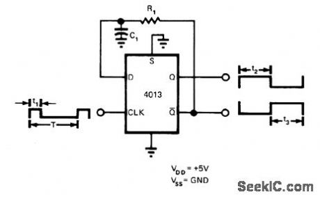
Single CMOS flip-flop generates approximately constant low-frequency signal from variable high-frequency signal. RC network in feedback loop determines output frequency, which is independent of rate at which flip-flop is clocked if output frequency is lowerthan dock frequency. If clock frequency is lower, output transitions occur at half of clock frequency. Provides two outputs, approxi-mately equal in duty cycle but opposite in phase. Circuit was developed to blink lamp at 1 Hz to indicate presence of active digital signal having variable duty cycle in range of 100 to 3000 Hz.-V. L. Schuck, Generate a Constant Frequency Cheaply, EDN Magazine, Aug, 20, 1975,p 80 and 82. (View)
View full Circuit Diagram | Comments | Reading(734)
TUNING_CAPACITOR_SIMULATOR
Published:2009/7/5 22:53:00 Author:May
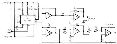
Fixed biasing network is used with Intersil 8038 variable-frequency sine-wave oscillator. Frequency is varied between 175 and 3500 Hz by circuit components forming capacitor simulator. Adjusting R3 varies equivalent capacitor value from 500 pF to 0.01 μF. Distortion is less than 1% overf requency range. Buffer opamp A5 provides high load impedanceto IC1 and low source impedance to variable-gain opamp A6. All opamps are 741.-R, Gunderson, Variable-Fre-quency Oscillator Features Low Distortion, EDN Magazine. Aug. 5. 1974. p 76 and 78. (View)
View full Circuit Diagram | Comments | Reading(670)
220_MHz_PHASE_LOCKED
Published:2009/7/5 22:51:00 Author:May
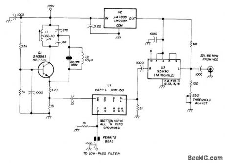
Fairchild 95H90 divide-by-10 counter U3 is used to divide 221.86-MHz VCO output frequency by 10. Resulting 22-MHz output of U3 is compared in phase with output of 22-MHz crystal-controlled oscillator by phase comparator U1, which is standard double-balanced mixer. Output of phase detector is passed through active low-pass filter for control of VCO. Article gives filter and VCO circuits. U2 is 5-V voltage regulator for 95H90.-H.Olson, Frequency Synthesizer for 220 MHz, Ham Radio, Dec. 1974, p 8-14. (View)
View full Circuit Diagram | Comments | Reading(918)
Interfacing_D_A_converters_with_HTL_CMOS_and_ECL
Published:2009/7/23 22:00:00 Author:Jessie
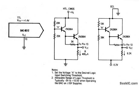
This circuit shows the interface circuits that are required to interface a typical TTL DAC (or similar IC) with ECL, HTL, and CMOS digital devices. Note that PMOS and NMOS devices can generally be interfaced with the CMOS, HTL circuit. (View)
View full Circuit Diagram | Comments | Reading(1588)
VHF_antenna_booster
Published:2009/7/23 21:56:00 Author:Jessie
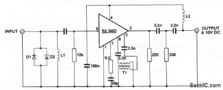
This circuit shows an SL560 amplifier connected as a wideband (40 to 260 MHz) antenna amplifier or booster suitable for any 50-Ω system. D1 and D2 are any general-purpose silicon diodes. L1 is 8 turns of #26, 1/8 intemal diameter.L2 is 20 turns of #26, 3/16 intemal diameter. T1 consists of two lengths of #34 wire approximately 6 long, twisted together (8 twists/inch) and wound on a 6-hole ferrite bead (Mullard FX1898). The circuit is powered through the coaxial cable (+10 V at the coax center, and ground at the coax outer shield), and requires about 30 mA. (View)
View full Circuit Diagram | Comments | Reading(681)
Linear Voltage Regulating Circuit of LTC1422
Published:2011/7/24 7:07:00 Author:Michel | Keyword: Linear Voltage, Regulating Circuit
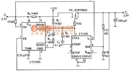
Picture 55 is linear voltage regulating circuit of LTC1422.When the input voltage Ui is added to the circuit,feet 2 of LTC1422 is high potential and feet 6 is low potential and the absorbing current is 10mA.At the time,VT1 stops and the output U。is zero.The phase input end (feet 1) voltage in LTC1422 comparator is zero.The output voltage in the comparator is lower than 1.232V reference voltage,thus feet 5 remains low PWL.After a timing cycle,the feet 6 of LTC1422 provides 1OμA for VT1.12V voltage is connected to feet 6 via R1 and it charges C1 with 1.2mA current via R2.R2 and C1 drops slowly and VT1 gate rises to limit impulsing current. (View)
View full Circuit Diagram | Comments | Reading(425)
C_WITH_VOM
Published:2009/7/5 22:47:00 Author:May
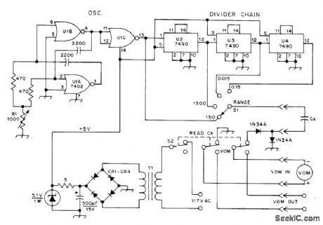
TTL-derived square-wave gen-erator U1 charges unknown capacitor CX to about 3.5 V at 285 kHz when using 150-μA scale of Heath MM-1 volt-ohm-milliammeter, to give 150-pF full-scale range. Larger values of capacitance are read by decreasing frequency with 7490 decade dividers. Use Mallory PTC401 for CR1-CR4. T1 is 6.3-VAC filament transformer. S2 restores normal VOM functions. Article gives design equations.-K. H. Cavcey, Read Capacitance with Your VOM,QST,Dec. 1975, p 36-37. (View)
View full Circuit Diagram | Comments | Reading(803)
PCD3341 Microcomputer Dialing Integrated Circuit
Published:2011/7/28 23:02:00 Author:Michel | Keyword: Microcomputer Dialing, Integrated Circuit

PCD3341 is the microcomputer integrated circuit, it is designed for communication equipment control and display, redial and storage dialing.
First,Functions Features
PCD3341 integrated circuit contains oscillator, keyboard input unit,column keyboard input unit, I2C bus interface control: ROM address counter,the ROM 3 KB read memory, ARM address counter,RAMM224KB read-only memory,eight timing counter, accumulators and test logic circuit, reset circuit,instruction registeration: control logic and interrupting logic etc .It uses an 8 bit CPU CPU, 224 KB of RAM, the 3KB programmable ROM,thus it saves energy very much. (View)
View full Circuit Diagram | Comments | Reading(587)
SEQUENTIAL_AC_FLASHER
Published:2009/7/5 22:44:00 Author:May

Uses simple ring counter in which triac gates form part of counter load. Incandescent lamps come on in sequence, with only one lamp normally on at a time. Pulse rate for switching lamp can be adjusted from about 1 every 0.1 s to 1 every 8 s.Circuit enclosed in dashed rectangle can be added to keep previous lamps on when next lamp is turned on. Only three stages are shown, but any number of additional stages can be added.- Circuit Applications for the Triac, Motorola, Phoenix, AZ, 1971, AN-466 p 11.
(View)
View full Circuit Diagram | Comments | Reading(1363)
10_pF_TO_1000_μF_DIGITAL
Published:2009/7/5 22:44:00 Author:May

Uses 555 timers as free-runnlng oscillators, one for gating and other as clock driving digital counter having fairchild FND507 4-digit display,Arrangement gives good accuracy without use of crystal oscillator,-W.H. Wang,Low-Cost Oscillators Build Accurate Capacitance Meter,Electronics,May 26, p 127 and 129. (View)
View full Circuit Diagram | Comments | Reading(572)
SWITCH_CONTROLLED_ADDER
Published:2009/7/5 22:44:00 Author:May

Direct BCD input from thumbwheel switch and use of standard crystal frequencies are primary advantages of accumulator stage of synthesizer, one decade of which is shown. BCD adder drives four D flip-flops whose outputs are fed back and added to switch states. Frequency range depends on number of decades used. Output pulse may be used directly for synchronization.If square wave is needed, clock frequency can be doubled and output of accumulator used to clock flip-flop.-D. W. Coulboum, Set Frequency Synthesizer with Thumbwheel Switches, EDN Magazine, April 5, 1975, p 115 and117. (View)
View full Circuit Diagram | Comments | Reading(3054)
2.5L Engine Control Sensor and Computer Connection Circuits of Beijing CHEROKEE Light Off-road Vehicle
Published:2011/7/24 7:35:00 Author:Michel | Keyword: CHEROKEE, Light Off-road Vehicle, Sensor, Computer Connection


In the picture, the engine controller (ECU) local is drawn up.The feet is connected to synchronous sensor. The end face plug-and-socket of the sensors express the wire location and its position in the manual can be checked.The plug has more than one contacting point and K4 belongs to the engine control (ECU) circuit.And computer has 8V power supply crankshaft position sensor and synchronous sensor. (View)
View full Circuit Diagram | Comments | Reading(776)
2.5L Engine Electronic Control Ignition Switch Wiring Circuit of Beijing CHEROKEE Light Off-road
Published:2011/7/24 7:58:00 Author:Michel | Keyword: CHEROKEE, Light Off-road, Ignition Switch, Wiring Circuit

In the circuit,ignition switch is drawn up.It is similar to general the ignition switch and it also has accessories (ACC,disconnect (OFF), operation (ON) and start (ST). The ignition switch has eight wires and connects to external circuit via plug-and-socket.And the wire of the electric plug-and-socket device is Gg2OGY/WT-sensor switch circuit 0.64 m ㎡ ash/white lines,G202OVT/YL sensor switch circuit- 0.64 m ㎡ purple/yellow line, All2RD-battery circuit 5 · 43 m ㎡ red line,A3812OR-battery circuit, one 5 43 m ㎡ orange line.And Al, A38 line is from power fusing wire Fll. (View)
View full Circuit Diagram | Comments | Reading(973)
LINEAR_OPTOCOUPLER_CIRCUIT_FOR_INSTRUMENTATION
Published:2009/7/5 22:39:00 Author:May

A dual optocoupler is used in a configuration which has the same current throughout as the LEDs. Assuming similar optocoupler features the output voltage must be equal to the noninverting input voltage. Since the op amp is within a closed loop the output voltage becomes equal to the input voltage. RC and C perform as a compensation network to prevent oscillations. (View)
View full Circuit Diagram | Comments | Reading(1592)
100_Hz_WIEN_BRIDGE
Published:2009/7/5 22:38:00 Author:May
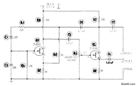


Simple RC-tuned oscillator uses only two resistors (R1 and R2) and two capacitors (C1 and C2) to set frequency.Feedback path covers both FET stages. Set R6 for best sine-wave output. For other audio frequencies, change value of R in ohms and C in farads in equation f = 1 /6.28RC where frequency is in hertz, R = R1 = R2, and C = C1 = C2.-R. P. Turner, FET Circuits, Howard W. Sams, Indianapolis, lN, 1977, 2nd Ed., p 48-50. (View)
View full Circuit Diagram | Comments | Reading(581)
7000_7999_MHz_PLL
Published:2009/7/5 22:37:00 Author:May
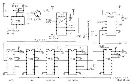
Provides output in 1-kHz steps under digital programming, except that first digit is hard-wired to 7 and does not change. VCO is Motorola MC4024, which generates square-wave output. For sineoutput, use low-pass filter at output of VCO to eliminate all frequencies above 7.999 MHz, or use different VCO. 74123 mono lengthens reset pulse generated by divide-by-N circuit. Terminals A, B, C, and D of 74192s go to grounding switches that are set to give desired division ratio, Article gives theory of PLL synthesizers YourseH!,73 Magazil,Oct,1977,p 182-188. (View)
View full Circuit Diagram | Comments | Reading(2269)
OPTICAL_COMMUNICATION_SYSTEM
Published:2009/7/5 22:36:00 Author:May
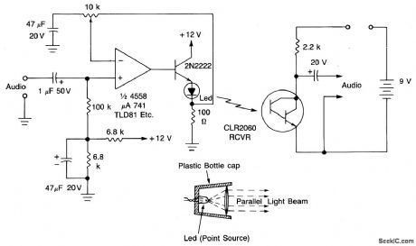
The circuit will modulate the light from the LED usmg a crystal cnicrophone or a loudspeaker output.To obtain the maximum range,the optical system must be efficient(see example),Either a convex lens or a concave mirror can be used to convert the LED output into a parallel beam.The received light is concentrated onto a sensitivephotodarlington transistor. At short range the signal across the load resistor is adequateto drive a crystal earpiece,for longer range an amplifier and a loudspeaker are needed. (View)
View full Circuit Diagram | Comments | Reading(1487)
| Pages:271/471 At 20261262263264265266267268269270271272273274275276277278279280Under 20 |
Circuit Categories
power supply circuit
Amplifier Circuit
Basic Circuit
LED and Light Circuit
Sensor Circuit
Signal Processing
Electrical Equipment Circuit
Control Circuit
Remote Control Circuit
A/D-D/A Converter Circuit
Audio Circuit
Measuring and Test Circuit
Communication Circuit
Computer-Related Circuit
555 Circuit
Automotive Circuit
Repairing Circuit