
Basic Circuit
Index 267
XR2240_XYNTHESIZER_
Published:2009/7/6 2:01:00 Author:May
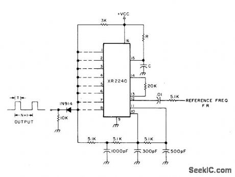
Circuit uses XR2240 programmable timer/counter for simultaneous multiplication of input frequency FR by factor of M and division of input frequency by factor of N + 1, where M and N are integers selected by appropriate connections of binary pins 1-8 to common output bus. Output frequency is then FR(M)/(1 + N) where M is between 1 and 10 inclusive and N is between 1 and 255 inclusive.VCC is 4-15 V.-H. M. Berlin, IC Timer Review, 73 Magazine, Jan. 1978, p 40-45. (View)
View full Circuit Diagram | Comments | Reading(1490)
TWO_DECADE_SCALER
Published:2009/7/6 1:59:00 Author:May
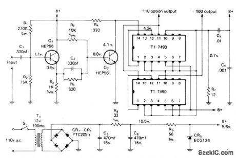
Solid-state frequency scaler extends range of older frequency counters by factors of 10 and 100, or up to 10 MHz for 100-kHz counter. Emitter-follower Q1 provides matching from high input impedance to low impedance for driving sensitive clipper Q2 that operates class B and presents 4 V P-P square wave to decade counter. Input accepts 1 to 14 V P-P.-D. Peck, A Solid State Scaler for Frequency Counters, CQ, April 1974, p 24-27.
(View)
View full Circuit Diagram | Comments | Reading(854)
15_GHz_PRESCALER
Published:2009/7/6 1:55:00 Author:May
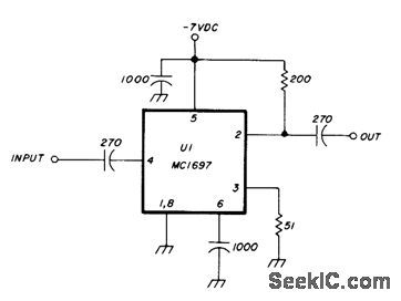
Motorola MC1697 IC provides division by 4 to extend operating range of 400-MHz counter above 1.5 GHz. Circuit will operate on input signals as low as 1 mW. Requires 60-mA power supply at -7 V.Article gives construction and test details.-J.Hinshaw, 1.5 GHz Divide-by-Four Presealer, Ham Radio, Dec, 1978, p 84-86. (View)
View full Circuit Diagram | Comments | Reading(746)
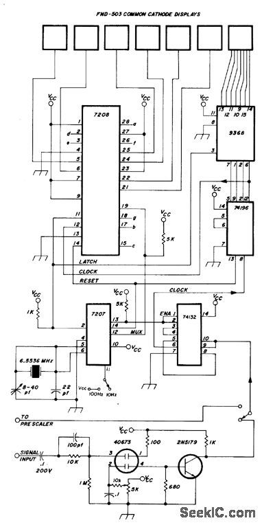
6_MHz_WITH_10_Hz_RESOLUTION
Published:2009/7/6 1:54:00 Author:May
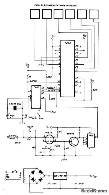
Intersil 7208 CMOS counter provides multiplexing of six digits in Fairchild display operating from 5-V regulated supply. Uses MOSFET 4673 input stage,-H, E. Harris, Simplifying the Digital Frequency Counter, Ham Radio, Feb, 1978, p 22-25. (View)
View full Circuit Diagram | Comments | Reading(668)
300_MHz_PRESCALER
Published:2009/7/6 1:50:00 Author:May
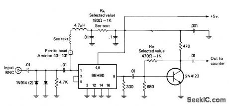
Uses Fairchild 95H90 IC to divide input signal frequency by factor of 10 up to 320 MHz. Full-wave diode limiter at input prevents damage to IC. RA is chosen to bias IC at point of maximum sensitivity; typical value is 680 ohms. Transistor amplifier provides 2-3 V P-P output. Bias resistor RB is set to make collector-base voltage 3 V; typical value is 620 ohms. Wind one lead of 4.7-ptH choke around nail 4 times, then remove nail and slip ferrite bead over end of wire before connecting it to pin 1. Keep all leads as short as possible. Article covers construction and alignment in detail.-I. Math, Math's Notes, CQ, May 1975, p 42-44 and 64. (View)
View full Circuit Diagram | Comments | Reading(4873)
5_MHz_FRONT_END
Published:2009/7/6 1:45:00 Author:May
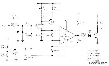
Used ahead of 5-MHz frequency counter to make input signal swing from logic 0 of 0 V to logic 1 of about 10 V as required for accurate counting of frequency for input signal having any input waveform shape and level. Input of front end has high impedance to minimize effect on input waveform. FET transistor Q1 and bipolar buffer Q2 drive Schmitt trigger using half of Motorola MC75:08 dual line receiver.-D. Aldridge, Battery-Powered 5-MHz Frequency Counter, Motorola, Phoenix, AZ, 1974, AN-717, p 5.
(View)
View full Circuit Diagram | Comments | Reading(2276)
SCHMITT_TRIGGER
Published:2009/7/6 1:43:00 Author:May
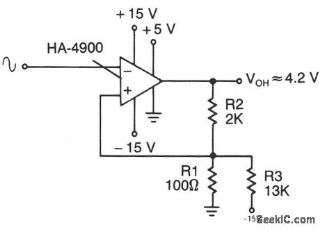
This circuit has a 100-mV hysteresis which can be used in applications where very fast transition times are required at the output, even though the signal input is very slow. The hysteresis loop also reduces false triggering because of noise in the input. (View)
View full Circuit Diagram | Comments | Reading(0)
30_MHz_WITH_10_Hz_RESOLUTION
Published:2009/7/6 1:40:00 Author:May

Simpl ified counter design using low chip count provides multiplexing of seven digits in Fairchild display, for applications where 1-Hz resolution is not needed. 7207 oscillator/timer gives counting interval of 0.1 s, for updating display 5 times per second. Article also gives circuit of 10:1 prescaler that increases frequency limit to 300 MHz, though with 100-Hz resolution. Total counter current drain is 300 mA from regulated 5-V supply.-H. E. Harris, Simplifying the Digital Frequency Counter, Ham Radio, Feb. 1978, p 22-25. (View)
View full Circuit Diagram | Comments | Reading(548)
TIME_BASE
Published:2009/7/6 1:38:00 Author:May
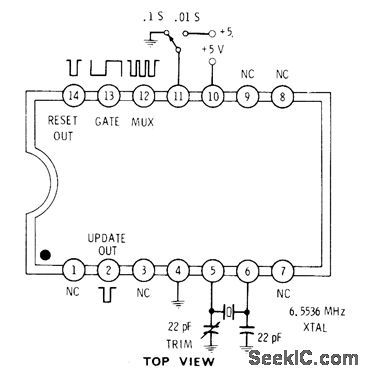
Intersil 7207 IC generates clock and housekeeping pulses required for frequency counter. With pin 11 grounded, gate output is high for 0.1 s and low for 0.1 s. With pin 11 high, gate is high 0.01 s and low 0.01 s.1.6-kHz square wave at pin 12 is useful for multiplexing displays. Update output is narrow negative-going pulse coincident with rising edge of gate output, for use in transferring countto display latches. Reset outputis used to reset counter.-D. Lancaster, CMOS Cook-book, Howard W. Sams, Indianapolis, IN, 1977, p 161. (View)
View full Circuit Diagram | Comments | Reading(981)
MINI_STEREO
Published:2009/7/6 1:35:00 Author:May
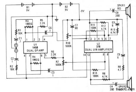
This circuit is built around two chips: the MC1458 dual op amp, configured as a preamplifier, and the LM378 dual 4-watt amplifier. The gain of the preamp is given by R3/R1 for one side and R4/R2 for the other side, which is about 100. That gain can be varied by increasing the ratios. The left and right channel inputs are applied to pins 2 and 6. The left and right outputs of U1 at pins 7 and 2 are coupled through C5/ R10 and C3/R6,respectively, to U2 to drive the two 8-Ωloudspeakers.
(View)
View full Circuit Diagram | Comments | Reading(2057)
50_MHz_WITH_1_Hz_RESOLUTION
Published:2009/7/6 1:33:00 Author:May
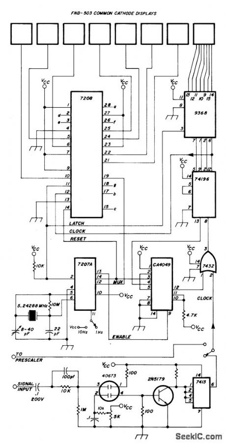
Combination of CMOS and TTL devices reduces chip count for digital frequency counter that provides 1-Hz resolution from below20 Hz to above 50 MHz. Use of 10:1 prescaler, also given in article, extends range to above 300 MHz with 10-Hz resolution. Uses Intersil 7208 CMOS seven-decade counter that includes multiplexor, decoder, drivers, and other controls for Fairchild FND.503 8-digit display. High-stability 5.24288-MHz crystal oscillator and frequency divider provide 1-s gate required for counting, outputs for synchronizing multiplexer, and short pulses for latching and resetting counters. Resolution can be decreased by factor of 10 by connecting pin 11 of 7207A to VCC, which is regulated 5 V.-H. E. Harris, Simplifying the Digital Frequency Counter, Ham Radio, Feb. 1978, p 22-25. (View)
View full Circuit Diagram | Comments | Reading(1030)
SCRATCH_RUMBLE_FILTER
Published:2009/7/6 1:30:00 Author:May

Single active filter provides two widely differing turnover frequencies, as required in audio amplifier used with phonograph. For values shown, insertion loss of filter is -6 dB at 37 Hz and at 23 kHz. Components may be switched to provide different turnover frequencies, but complete removal of filter requires considerably more complicated switching.-P. I. Day, Combined Rumble and Scratch Filter, Wireless World, Dec. 1973, p 606. (View)
View full Circuit Diagram | Comments | Reading(800)
CERAMIC_CARTRIDGE_SYSTEM
Published:2009/7/6 1:29:00 Author:May
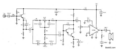
Circuit using National LM389 opamp having three transistors on same chip provides required high input impedance for ceramic cartridge because input transistor is wired as high-impedance emitter-follower. Remaining transistors form high-gain Darlington pair used as active element in low-distortion Baxandall tone-control circuit.-“Audio Handbook,” National Semiconductor, Santa Clara, CA, 1977, p 4-33-4-37. (View)
View full Circuit Diagram | Comments | Reading(1468)
20_Hz_HIGH_PASS_RUMBLE_FILTER
Published:2009/7/6 1:28:00 Author:May

Second-order rumble filter for phonograph amplifier has 1-dB peak and 20-Hz cutoff frequency. Design uses large resistance values to permit use of smaller and lower-cost capacitors.-D. Lancaster, Active-Filter Cookbook, Howard W, Sams, Indianapolis, IN, 1975, p 191-192. (View)
View full Circuit Diagram | Comments | Reading(718)
SCRATCH_FILTER
Published:2009/7/6 1:25:00 Author:May

Provides passband gain of 1 and corner frequency of 10 kHz for rolling off excess high-frequency noise appearing as hiss, ticks, and pops from worn records. Design procedure is given.- Audio Handbook, National Semiconductor, Santa Clara, CA, 1977, p 2-49-2-52. (View)
View full Circuit Diagram | Comments | Reading(1382)
RUMBLE_SCRATCH_FILTER
Published:2009/7/6 1:24:00 Author:May

Used after pre-amp in high-quality audio system to improve reproduction of phonograph records. Two-pole Butterworth design has switchable breakpoints providing any desired degree of filtering.- Signetics Analog Data Manual, Signetics, Sunnyvale, CA, 1977, p 638-639. (View)
View full Circuit Diagram | Comments | Reading(1928)
NEW_RIAA_NETWORK
Published:2009/7/6 1:24:00 Author:May
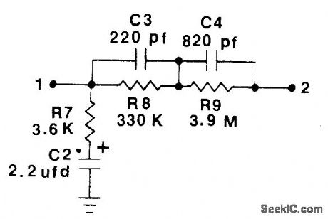
Values of R7 and C2 have been changed as shown in standard net-work for phonograph playback equalization. Tantalum electrolytic rated at least 20 V is recommended for C2. Network can also be used as inverse RIAA equalizer for testing preamps, with signal applied to terminal 2 and output to preamp taken from terminal 1. New standard extends playback equalization to 20,000 Hz and specifies that equalization be 3 dB down from previous standard at 20 Hz, with rolloff at 6 dB per octave below 20 Hz.-W. M. Leach, New RIAA Feedback Network, Audio, March 1978, p 103. (View)
View full Circuit Diagram | Comments | Reading(789)
FASTER_PHASE_LOCK
Published:2009/7/6 1:15:00 Author:May

Circuit was developed to reduce the normally long acquisition time of phase-locked loops when measuring frequency of short signal bursts. Synchronization of VCO to input phase allows correction pulses to be developed in correct polarity only, to give lockup time less than 10 cycles of input when using idling frequency of 12 kHz for VCO. Input signals are compared to those of VCO at EXCLUSIVE-OR gate A. Gating of error pulses by gate F and flip-flop G-H allows I or J to drive current pulses of correct polarity into C1. Voltage correction on C1, controlled by values of R2 and R3, is proportional to width of error pulses. Article covers circuit operation in detail.-R. Bohlken, A Synchronized Phase Locked Loop, EDN Magazine, March 20, 1973, p 84-85. (View)
View full Circuit Diagram | Comments | Reading(768)
VOLTAGE_FEEDBACK
Published:2009/7/6 1:14:00 Author:May
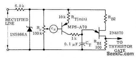
Used when quantity to be sensed is isolated varying DC voltage es such as output of tachometer. Operating point is determined by setting of RC. Output of voltage feedback circuit goes to thyristor in series with load.-D. A. Zinder, Unijunction Trigger Circuits for Gated Thyristors, Motorola, Phoenix, AZ, 1974, AN-413, p 4. (View)
View full Circuit Diagram | Comments | Reading(697)
SHIFTING_AND_SQUARING
Published:2009/7/6 1:13:00 Author:May
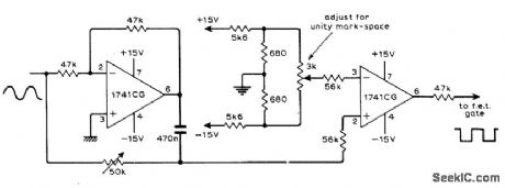
Circuit uses two opamps to derive phase-shifted reference square wave and DC output signal of phase-sensitive detector from same sine-wave signal source. Article gives theory of operation and waveforms for various operating conditions.-G. B. Clayton, Experiments with Operational Amplifiers, Wireless World, July 1973, p 355-356. (View)
View full Circuit Diagram | Comments | Reading(651)
| Pages:267/471 At 20261262263264265266267268269270271272273274275276277278279280Under 20 |
Circuit Categories
power supply circuit
Amplifier Circuit
Basic Circuit
LED and Light Circuit
Sensor Circuit
Signal Processing
Electrical Equipment Circuit
Control Circuit
Remote Control Circuit
A/D-D/A Converter Circuit
Audio Circuit
Measuring and Test Circuit
Communication Circuit
Computer-Related Circuit
555 Circuit
Automotive Circuit
Repairing Circuit