
Basic Circuit
Index 281
CW_FILTER_FOR_INTERFERENCE
Published:2009/7/3 3:41:00 Author:May
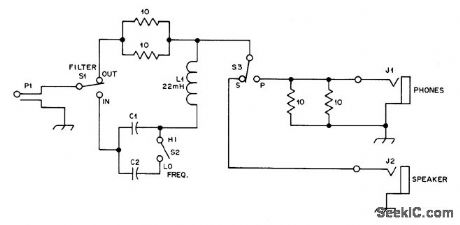
Audio bandpass filter, designed for connection between loudspeaker jack of receiver and external loudspeaker or phone, has half-power bandwidth of about 70 Hz but rolls off gradually without causing ringing, Series LC combination, connected in hot line to loudspeaker,looks like 5-ohm re sistance at resonance, cutting signal amplitude about in half. At Iower frequencies filter looks like large capacitive reactance and at higher frequencies it resembles large inductive reactance, both causing high attenuation. Filter thus discriminates against all except switch-selected resonant frequency, either 760 or 1070 Hz.Choose best frequency for particular receiving situation by trial.-F. Noble, A Passive CW Filter to improve Selectivity, QST, Nov. 1977, p 34-35. (View)
View full Circuit Diagram | Comments | Reading(1154)
DIGI_TACH
Published:2009/7/3 3:40:00 Author:May
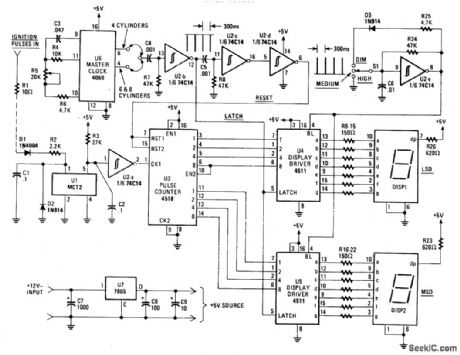
The Digi-Tach contains a master-clock circuits (U6), latch and reset pulse generators (U2-b-U2-d), input signal conditioner (U1, U2-a), pulse counter (U3), display and display drivers (DIS1, DIS2, U4, and U5), and a voltage regulator (U7). As an added feature, Digi-Tach contains a dimmer circuit (U2-e). (View)
View full Circuit Diagram | Comments | Reading(1634)
GENERAL_PURPOSE_RF_DETECTOR
Published:2009/7/3 3:40:00 Author:May
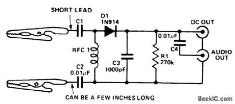
Circuit NotesThis circuit provides a dc output to a meter and an audio output (if necessary) for checking transmitters or modulated signals. It can be used also as a field strength meter or transmitter monitor. (View)
View full Circuit Diagram | Comments | Reading(988)
60_Hz_TUNABLE_NOTCH
Published:2009/7/3 3:39:00 Author:May
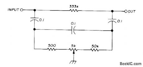
Can be used to minimize hum pick up from AC line. Circuit tunes from 40 to 120 Hz with single pot. Artide gives design equations. With unmeasured ceramic disk capacitors and 5% resistors, notch depth at 60 Hz was 44.5 dB. By selecting capacitors with equal values and replacing 333K with 500K trimpot, careful adiustment increases notch depth to 57 dB.-C. Hall, Tunable RC Notch Filter, Ham Fladio, Sept. 1975, p 16-20. (View)
View full Circuit Diagram | Comments | Reading(612)
505_MHz_BANDPASS
Published:2009/7/3 3:39:00 Author:May
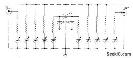
Provides 60% band-width with only 4-dB insertion loss Each coil is about 2.2μH,and trimmer capacitors are 1.5-7 pF Sweep signal generator and 5-in CRO are essential for alignment.-P. H.Sellers, 50-MHz Bandpass Filter, Ham Radio, Aug. 1976, p 70-71. (View)
View full Circuit Diagram | Comments | Reading(700)
SINGLE_INJECTOR_TRACER
Published:2009/7/3 3:38:00 Author:May
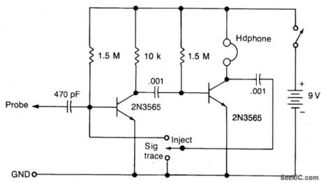
Circuit NotesThis circuit will provide a nominal square wave output in the audio range in the Inject mode, the harmonics of which should be heard at several MHz. In the Trace mode the non-linear operation of the amplifter will detect modulated rf signals which will be filtered by the.0.01μF capacitor and heard in the headphones. (View)
View full Circuit Diagram | Comments | Reading(441)
ELLIPTIC_HIGH_PASS_LOW_PASS
Published:2009/7/3 3:38:00 Author:May
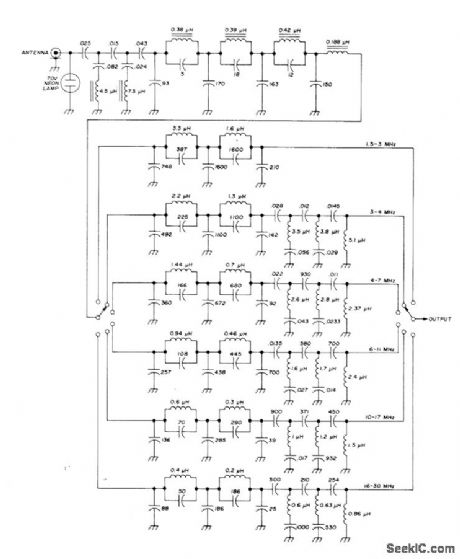
Covers 1.45 to 32 MHz in six steps, for use at front end of high-frequency communication receiver to suppress unwanted broadcast signals. Low-pass filter section, acting with one of six following low-pass sections, gives over 90-dB image suppression. Special Bessel-Cauer elliptic filter having Chebyshev response in passband provides required 50-ohm impedance matching so filters can be cascaded.-U. L. Rohde, Optimum Design for High-Frequency Communications Recoivers, Ham Fladio, Oct. 1976, p 10-25.
(View)
View full Circuit Diagram | Comments | Reading(1123)
DELAY_CIRCUITS_FOR_HEADLIGHTS
Published:2009/7/3 3:33:00 Author:May
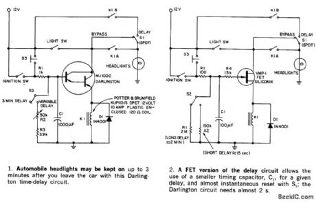
This circuit keeps an automobile's headlights on temporarily. It also will turn the lights off, even if you forget to flip the light switch. The circuit's shut-off delay is actuated only after both the ignition and light switches have been on, and only if the ignition switch is tumed off first. If the light switch is tumed off ftrst, no delay results. Parking and brake-light operation is not affected. The maximum time out can be up to 3 minutes in part 1 and hours with the circuit in part 2, depending on the relay selected and the value of R2. A switch S2 can be used to permit selection of either a short or long delay.Momentary switch S3 can restart circuit timing before the time-out is completed. A bypass switch, S1 removes the delay action. (View)
View full Circuit Diagram | Comments | Reading(514)
TWIN_LED_TUNING_INDICATOR
Published:2009/7/3 3:33:00 Author:May
Provides maximum sensitivity at correct tuning point and indicates direction of mistuning. Both lamps are in feedback loop of one opamp, connected to serve as highlysensitive null detector.When set is tuned correctly, output of this opamp is at midpoint of supply voltage and neither LED is lit. Circuit is used with RCA CA3089 IF chip in which AFC output is a current. Capacitor across first 741 opamp removes modulation components from this input.-M. G. Smart, F.M. Tuning Indicators, Wireless World,Dec.1974,p 497. (View)
View full Circuit Diagram | Comments | Reading(1217)
MICROVOLT_PROBE
Published:2009/7/3 3:33:00 Author:May
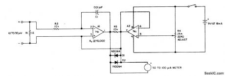
Circuit NotesThe current tracer helps locate a defective IC that is loading down the power supply. The tracer amplifies the small voltage drop caused by current flow along a fraction of an inch of PC wiring and drives an ordinary microammeter. Needle-point test probes are used to contact the edge of a PC trace and to follow the current to determine which branch the current takes. One-half of a dual 741 op amp forms a dc amplifter with ac feedback to prevent oscillations and hum-pickup problems. It drives a 50-to-100 μA me-ter. The other op amp provides a center tap for the 9 V battery supply and zero adjustment with R4. Two diodes protect the meter. Resistor R1 eliminates the necessity for shorting the probes when the meter is zeroed. The value of 1 ohm is large when compared with the resistance of the meter leads plus the bridged portion of PC wiring. (View)
View full Circuit Diagram | Comments | Reading(1161)
MULTIMETER_FOR_BLIND
Published:2009/7/3 3:30:00 Author:May
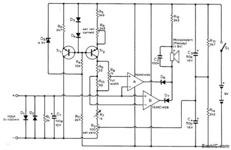
Uses small electric horn to produce sound when DC voltage being measured is different from reference voltage value determined by setting of linear wirewound pot R7. Blind person adjusts R7 for null in sound, then reads Braille dots for that setting to get value of voltage being measured. Use PNP silicon transistors, such as BC177 or BC187.D5 is 4.3.V 400W zener, such as BZX79/CAV3.Other diodes are small-signal silicon, sueh as BA100 or 1N914A.-G. P. Roberts, Multimeters for Blind Students, Wireless World, April 1974, p73-74. (View)
View full Circuit Diagram | Comments | Reading(1038)
HEADLIGHT_DIMMER
Published:2009/7/3 3:29:00 Author:May
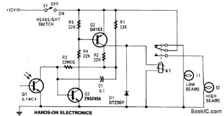
When the lights of an on-coming car are sensed by photo-transistor Q1, things get going. Sensitivity is set by the 22-megohm resistor, R5, to about half a foot-candle. The relay used has a 12-volt, 0.3A coil. The L14C1 is complete with a lens that has a diameter of one inch for a 10° triewing angle. (View)
View full Circuit Diagram | Comments | Reading(1160)
MOSFET_RF_STAGE_
Published:2009/7/3 3:26:00 Author:May
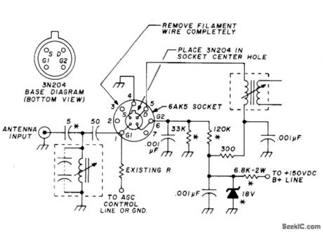
Changing 6AK5 tube to 3N2O4 dual-gate MOSFET improves sensitivity and lowers noise in older VHF FM communication receiver using tubes. Break off center grounding pin of tube socket and cut wires soldered to pin, then connect transistor circuit to tube socket as shown. Replace original resistor going to pin 6 with 120K and run 37K resistor from pin 6 to ground. Move antenna input lead to top of RF input coil, and remove 6-V filament wiring from socket. If tube filaments were in series, replace 6AK5 filament with 36-ohm 2-W resistor. Conversion increases sensitivity to 0.3μγ for 20-dB quieting.-H. Meyer, How to Improve Receiver Performance of Vacuum-Tube VHF-FM Equipment, Ham Fladio, Oct. 1976, p 52-53. (View)
View full Circuit Diagram | Comments | Reading(1643)
DEMODULATOR
Published:2009/7/3 3:18:00 Author:May

XR-215 PLL IC connected for frequency-seleetive demodulation of FM signals. Value of C0 depends on carrier frequency. C1 detgmines selectivity; for 1-10 MHz, range of C1 is 10-30 times C0. For operation below 5 MHz, RX can be opened; above 5 MHz, use about 75O ohms. - Phase-Locked Loop Data Book, Exar Integrated Systems, Sunnyvale, CA, 1978, p 21-28. (View)
View full Circuit Diagram | Comments | Reading(766)
FSK_DEMODULATOR_FOR_EKG_RELAY
Published:2009/7/3 3:15:00 Author:May
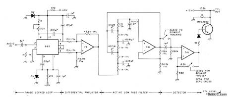
Used at receiving end of satellite system for relaying EKGs, to convert received audio FSK signal to TTL level-shifting output from which original EKG can be obtained. Phase-locked loop tracks input signal frequency and feeds appropriate error signal through differential amplifier to five-pole Butterworth low-pass filter having 1500-Hz cutoff. DC offset is removed by capa-itor coupling, for use in zero-crossing detector or Schmitt-trigger detector. Signal is next converted into TTL-compatible level. Recorded output could not be distinguished from original EKG by doctors.-D. Nelson, Medical Data Relay via Oscar Satellite, Ham Fladio, April 1977, p67-73. (View)
View full Circuit Diagram | Comments | Reading(1156)
VARICAP_TUNER_
Published:2009/7/3 3:10:00 Author:May
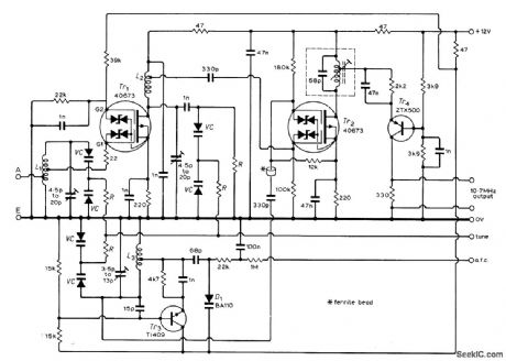
Uses silicon variable-capacitance diodes to provide voltage tuning over FM band of 87.5 to 108 MHz. Article covers construction and adjustment and gives circuit of stable noise-free regulated power supply that also provides required DC tuning voltage of 2 to 30 V. All six varicap diodes are Siemens BB103 of same color selection (all green or all blue).Resistors R can be any value between l00k and1 megohm.-L.Nelson-Jones,F.M.Tuner Design-Two Υears Later, Wireless World, June1973,p 271-275 (View)
View full Circuit Diagram | Comments | Reading(1941)
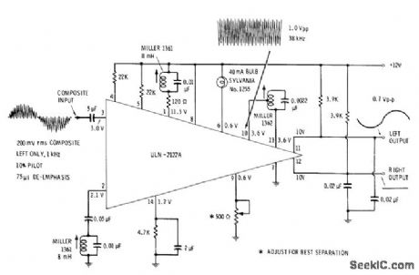
SPEECH_SYNTHESIZER
Published:2009/7/3 3:05:00 Author:May


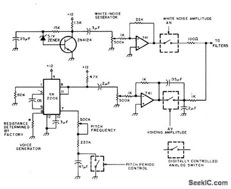
Based on analog simulation of vocal tract. Rush of air through vocal passages is simulated by white-noise generator, while action of larynx is simulated in lower branch of circuit. Article covers problems involved in achieving transitions from phoneme to phoneme, along with automatic emphasis of leading or terminating consonants and intonation of rhythm associated with importance or placement of word in speech. ASCII symbols are given for 33 phonemes generated in A1Cybernetic Systems model 1000 speech synthesizer, which uses circuit shown in combination with 10 active filters composed of 15 opamps, vocal excitation circuits, ASCII character decoders, and phoneme memories.-W. Atmar, The Time Has Come to Talk, Byte, Aug. 1976, p 26-30 and 32-33 (View)
View full Circuit Diagram | Comments | Reading(918)
LOW_COST_SPEED_REGULATOR_FOR_DC_MOTORS
Published:2009/7/3 3:05:00 Author:May
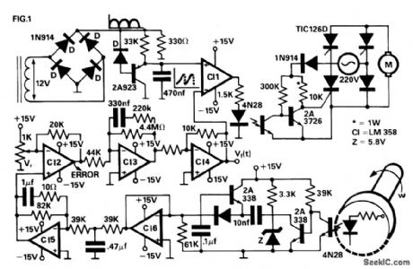
A four thyristor controlled bridge is used for operation in two quadrants of the torquespeed characteristics. In the trigger circuits the usual pulse transformers were replaced by self biased circuits which minimize gate power consumption and increase noise immunity. Electrical isolation is guaranteed by the use of optocouplers. The trigger pulses are generated by the comparison between an error signal, previously processed and amplified, and a line synchronism signal. The converter's output is a dc voltage proportional to the speed, which after being compared with a reference signal, becomes the error signal. (View)
View full Circuit Diagram | Comments | Reading(1313)
STEPPING_MOTOR_DRIVER
Published:2009/7/3 3:03:00 Author:May
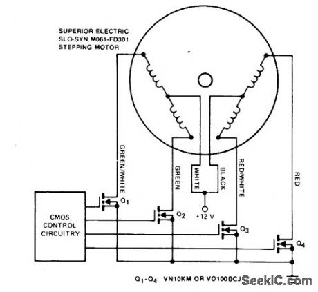
Stepping motors find wide use in disk drives and machine control. MOSPOWER transistors are ideal motor drivers because of their freedom from second breakdown. Note that snubbing networks are not used because load line shaping is not necessary with MOSPOWER and the inductance of the motor is fairly low so that the inductive spike is small. The MOSFET gates are tied directly to the outputs of the CMOS control circuitry. The logic is arranged to sequence the motor in accordance with the needs of the application. (View)
View full Circuit Diagram | Comments | Reading(807)
1_kHz_BANDPASS_HIGH_Q
Published:2009/7/3 3:02:00 Author:May
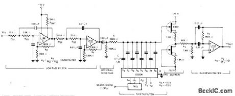
Shunt-switched bandpass filter with o of 1000 and voltage gain of about 7 uses DG508 CMOS multiplexer containing required analog switches,interface cicuhs, and deoode logic for 8-path filter. Bandwidth for 3 dB down is 1 Hz centered on 1 kHz, with asymptotic slope of 6 dB per octave. Clock controls shunt-switched filter action.- Analog switches and Their Applications, Siliconix,Santa Clara,CA,1976,p 5-12-5-14. (View)
View full Circuit Diagram | Comments | Reading(973)
| Pages:281/471 At 20281282283284285286287288289290291292293294295296297298299300Under 20 |
Circuit Categories
power supply circuit
Amplifier Circuit
Basic Circuit
LED and Light Circuit
Sensor Circuit
Signal Processing
Electrical Equipment Circuit
Control Circuit
Remote Control Circuit
A/D-D/A Converter Circuit
Audio Circuit
Measuring and Test Circuit
Communication Circuit
Computer-Related Circuit
555 Circuit
Automotive Circuit
Repairing Circuit