
Basic Circuit
Index 289
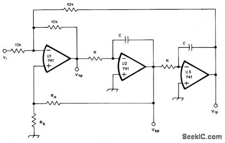
1_Hz_STATE_VARIABLE_FILTER
Published:2009/7/2 8:46:00 Author:May


Universal filter has simultaneous low-pass, bandpass, high-pass, and notch outputs all with cutoff frequency of 1 Hz. To scale circuit up to 1-kHz cutoff, replace 10-megohm resistors with 10K.-D.Lancaster, CMOS Cookbook, Howard W.Sams, Indianapolis, IN, 1977, p 343-344. (View)
View full Circuit Diagram | Comments | Reading(841)
20_kHz_BANDPASS
Published:2009/7/2 8:44:00 Author:May

Provides bandwidth of 2000 Hz and midband gain of 1 for applications requiring narrow-bandwidth bandpass active filter. Design procedure is given.- Audio Handbook, National Semiconductor, Santa Clara, CA, 1977, p 2-52-2-53. (View)
View full Circuit Diagram | Comments | Reading(954)
1__kHz_THREE_FUNCTION
Published:2009/7/2 8:42:00 Author:May

Three-function fixed-frequency active filter uses three sections of RCA CA3401E, Motorola MC33OlP, or National CA3401E quad opamp. Circuit uses highvalue series resistors for noninverting inputs to limit bias current to between 10 and 100,μA.-P. A. Lovelock, Discrete Operational Amplifier Active Filters, Ham Radio, Feb. 1978, p 70-73. (View)
View full Circuit Diagram | Comments | Reading(517)
3_1_TRACKING_FILTER
Published:2009/7/2 8:40:00 Author:May

Connection shown for Exar XR-215 PLL IC tracks input signal over 3:1 frequency range centered on free,running frequency of VCO. Tracking range is maximum when pin 10 is open. R0 is typically between 1K and 4K.C1 is between 30 and 300 times C0 where timing capacitor C0 depends on center frequency. System can also be operated as linear discriminator or analog frequency meter covering same 3:1 change of input frequency. RF can be 36K.- Phase-Locked Loop Data Book, Exar Integrated Systems, Sunnyvale, GA, 1978, p 21-28. (View)
View full Circuit Diagram | Comments | Reading(761)
STATE_VARIABLE_DESIGN
Published:2009/7/2 8:38:00 Author:May
Universal filter network using three opamps can provide low-pass, high-pass, or bandpass audio response for CW and SSB reception. Filter uses one summing block U1, two identical integrators, U2 and U3, and one damping network. Cutoff frequencies are same as center frequency for bandpass response. Article gives design equations and graph for choosing values to give optimum performance for type of response desired, For unity-gain second-order Butterworth filter with low-pass or high-pass cutoff of 700 Hz, R is 6800 ohms and C is 0.033 μF. Q must be fixed at 0.707 and RA must equal 1.12 × RB. Thus, if RB is 2700 ohms, RA should be 3OOO.-H. M. Berlin, The State-Variable Filter, QST, April 1978, p 14-16. (View)
View full Circuit Diagram | Comments | Reading(696)
3_kHz_NOTCH
Published:2009/7/2 8:37:00 Author:May
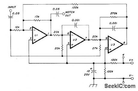
Uses three sections of National LM324 quad opamp to provide fixed center frequency of 3 kHz for notch. Single supply can be 5-25 V.-P. A. Lovelock, Discrete Operational Amplifier Active Filters, Ham Radio, Feb. 1978, p 70-73. (View)
View full Circuit Diagram | Comments | Reading(785)
OPTIMIZING_CMR
Published:2009/7/2 8:26:00 Author:May
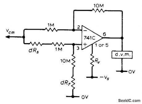
Article covers procedures for optimizing common-mode rejection when opamp is used to drive digital voltmeter. Value of Rv is determined by using resistance box connected between negative supply and pin 1 or 5 while other pin is shorted to negative supply, choosing pin which gives voltage swing in right direction on meter, then adiusting resistance box for zero output. Resistance box is similarly used at dR5 and dRf locations.-R. J. lsaacs, Optimizing OpAmps. Wireless World. April 1973. p 185-186. (View)
View full Circuit Diagram | Comments | Reading(512)
12_μH_GYRATOR
Published:2009/7/2 8:19:00 Author:May
Two RCA opamps in gyrator loaded with 10μ capacitor give effective 12-μH inductor that remains constant in value over rangefrom lOHz to almost 1 MHz.Q varies from 1 at l0Hz to maximum of 500 at 10 kHz,Article gives design equations.-A C Caggiano Simple Gyrator for L from C.EEE Magazine.Aug 1970.p 78. (View)
View full Circuit Diagram | Comments | Reading(752)
2_20_kHz_SELF_TUNING_BANDPASS
Published:2009/7/2 8:13:00 Author:May

Center frequency of filter is automatically adjusted to track signal frequency, for optimum noise rejection when input frequency varies over wide range as it does with many types of vibrating transducers.Requires no reference frequency and no intemal oscillator or synchronizing circuits. Flequency range can be extended in decade steps by capacitor switching. When filter is not tuned to input frequency, phase shift is not 180° and phase detector applies error signal to gate of FET to control its drain-source resistance. Phase detector A4-A5-CR2-CR3 and FET form part of negative-feedback loop around filter, so error in phase changes resistance of FET and thereby retunes filter, Article gives design equations, operational details, and waveforms at various points in circuit.-G. J. Deboo and R.C. Hedlund, Automatically Tuned Filter Uses IC Operational Amplifiers, EDN/EEE Magazine, Feb.1, 1972, p 38-41. (View)
View full Circuit Diagram | Comments | Reading(915)
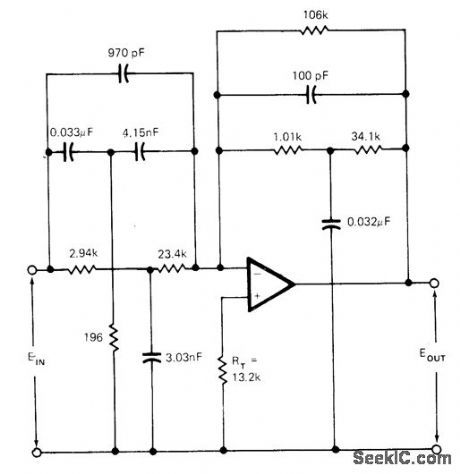
75O_Hz_SIXTH_ORDER_BANDPASS
Published:2009/7/2 8:12:00 Author:May

Provides passband gain of 6 (15.6 dB) and Q of 8.53 by cascading three identical second-order filter sections. Each section uses multiple feedback.-H. M.Berlin, Design of Active Filters, with Experiments, Howard W. Sams, Indianapolis, IN, 1977, p 147-148. (View)
View full Circuit Diagram | Comments | Reading(808)
150_Hz_HIGH_PASS
Published:2009/7/2 8:10:00 Author:May

Circuit includes variable high-frequency source supplying triangle-wave input to filter for demonstrating high-pass action. If long supply leads cause oscillation, connect 0.1-μF capacitors between ground and supply pins 4 and 7 as shown.-F. M. Mims, lntegrated Circuit Projects, Vol. 4, Radio Shack, Fort Worth, TX, 1977, 2nd Ed., p 87-94. (View)
View full Circuit Diagram | Comments | Reading(935)
LOW_COST_FET_INPUT
Published:2009/7/2 8:09:00 Author:May

Uses two 2N3819 FETs as differential source-follower operated at constant source current of 200μ A provided by Tr1.and Tr2. Input performance is comparable to that of more expensive commercial units. Match FETs to reduce thermal drift. Trim input offset voltage to zero by adding resistor in appropriate FET source. Input impedance of circuit is greater than 1013 ohms.-J. Setton. F.E.T.-Input Operational Amplifier. Wireless World. Nov. 1976. p 61. (View)
View full Circuit Diagram | Comments | Reading(696)
18_dB_PER_OCTAVE_EMPHASIS
Published:2009/7/2 8:09:00 Author:May
Circuit shown is result of design procedure given in article for active filter that provides frequency emphasis at rate of 18 dB per octave between 5 and 15 kHz, Emphasis does not exceed 40 dB at 20 kHz.Design equations include parameters for closed-loop gain of opamp. Scale factor is applied to input and feedback networks individually after design, to give reasonable eomponent values.-B. Brandstedt, Tailor the Response of Your Active Filters, EDN magazine, March 5, 1973, p 68-72. (View)
View full Circuit Diagram | Comments | Reading(561)
300_3000_Hz_WIDEBAND
Published:2009/7/2 8:07:00 Author:May

Used in voice communication systems where signals below 300 Hz and above 3000 Hz must be rejected. Secondorder Butterworth stopband responses are achieved by combining low-pass and high-pass sections of equal-component voltage-controlled voltage-source filters. Overall passband gain is 8 dB Opamps can be 741.-H. M. Berlin, Design of Active Filters, with Experiments, Howard W. Sams, Indianapolis, IN, 1977, p 148-151. (View)
View full Circuit Diagram | Comments | Reading(1321)
480_kHz_LOW_PASS
Published:2009/7/2 8:07:00 Author:May

Butterworth low-pass active filter uses pair of dual opamps with external resistors and capacitors to give corner frquency of 480 kHz and output impedance level of 1K. Article presents design procedure in detail and gives frequency response curve.-L. T.Burton and D.Treleaven, Active Filter Design Using Generalized Impedance Conveners, EDN Magazine,Feb.5,1973, p 68-75. (View)
View full Circuit Diagram | Comments | Reading(797)
13O_V_P_P_DRIV
Published:2009/7/2 8:00:00 Author:May
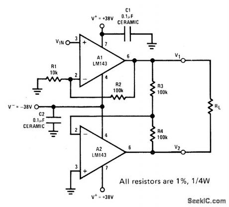
Two LM143 high-voltage opamps operating from 38-V supply can provide up to 138 V P-P undipped into 10K floating Ioad when connected as shown to give noninverting voltage amplifier followed by unity-gaininverter. Power supplies should be bypassed to ground with 0.1-μF capacitors. - Linear Applications, Vol. 2. National Semiconductor, Santa Clara. CA. 1976. AN-127. p 1-3. (View)
View full Circuit Diagram | Comments | Reading(556)
VARIABLE_DEAD_BAND_RESPONSE
Published:2009/7/2 7:44:00 Author:May
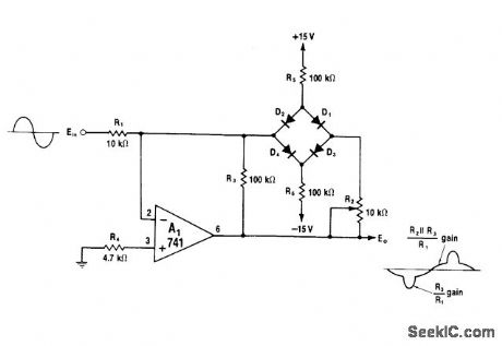
Diode bridge in feedback loop of opamp provides controlled amount of dead-band response. As value of R2 is increased from 0 ohms, voltage developed across R2. serves to raise dead-band level at which bridge opens and circuit amplifies with normal gain of R3/R1. Below dead-band level. bridge is blocked and circuit gain is equal to parallel combination of R2 and R3 divided by R1. Use matched diodes such as CA3O19 for peaks below ±7 V; for higher peaks,.use 1N914s.-W.G. Jung, IC Op-Amp Cookbook, Howard W.Sams. Indianapolis IN.1974. p 207. (View)
View full Circuit Diagram | Comments | Reading(1238)
CONTROLLABLE_12_dB_PER_OCTAVE_ROLLOFF
Published:2009/7/2 7:43:00 Author:May
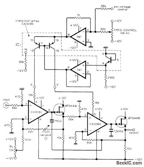
Frequency at which rolloff starts can be set in range between 15 and 15,000 Hz by extemal voltage or current. If only manual control of frequency is required, short points X and Y and conned them to wiper of 10,000-ohm logarithmic potentiometer that is positioned between -12 V and ground.-T.Orr, Voltage/Current Controlled Filter, Wireless World,Nov.1976, p 63. (View)
View full Circuit Diagram | Comments | Reading(560)
100_Hz_HIGH_PASS
Published:2009/7/2 7:41:00 Author:May
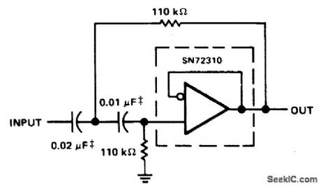
Metallized polycarbonate capacitor are required for good temperature stability in high-pass active filter using voltage-follower opamp. Cutoff frequency is 100 Hz.- The Linear and Interface Circuits Data Book for Design Engineers, Texas instruments, Dallas, TX, 1973, p 4-39. (View)
View full Circuit Diagram | Comments | Reading(489)
ACTIVE_AF_FOR_SSB_AND_CW
Published:2009/7/2 7:40:00 Author:May
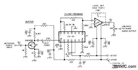
Uses Kinetic Technology FX-60 IC (culled from FS-60, FS-65, and FS-61 production by manufacturer) as 2.5-kHz tunable detected-audio low-pass filter for SSB. Provides inexpensive hybrid active filter using multiloop negative feedback for low-pass transfer functions. External resistors tune filter frequency and give choice of Q. High-impedance buffer Ql provides nominal gain while isolating filter from previous receiver stages.Opamp U2 boosts overall gain.-M. A. Chapman, Audio Filters for Improving SSB and CW Reception,Ham Radio,Nov.1976,p 18-23. (View)
View full Circuit Diagram | Comments | Reading(2907)
| Pages:289/471 At 20281282283284285286287288289290291292293294295296297298299300Under 20 |
Circuit Categories
power supply circuit
Amplifier Circuit
Basic Circuit
LED and Light Circuit
Sensor Circuit
Signal Processing
Electrical Equipment Circuit
Control Circuit
Remote Control Circuit
A/D-D/A Converter Circuit
Audio Circuit
Measuring and Test Circuit
Communication Circuit
Computer-Related Circuit
555 Circuit
Automotive Circuit
Repairing Circuit