
Basic Circuit
Index 290
60_Hz_ADJUSTABLE_Q_NOTCH
Published:2009/7/2 7:37:00 Author:May
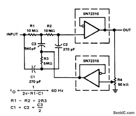
Connection shown for two SN72310 voltage-follower opamps provides attenuation of 60-Hz power-line frequency. Setting of R4 determines a of filter.- The Linear and Intelface Circuits Data Book for Design Engineers, Texas Instruments, Dallas, TX, 1973, p 4-39. (View)
View full Circuit Diagram | Comments | Reading(447)
NARROW_BANDPASS_FOR_SPEECH
Published:2009/7/2 7:36:00 Author:May

Simple audio filter provides about 20-dB gain at bandwidth of 80 Hz Bandwidth can be narrowed tolimits of unintelligibility by adjusting 10K pot.Input is plugged into phone jack of receiver, and headphones are connected to output. Transistors are SK3004 or equivalent.-Circuits, 73 Magazine, Jan.1974 p 125. (View)
View full Circuit Diagram | Comments | Reading(876)
VARIABLE_Q_FOR_CW
Published:2009/7/2 7:35:00 Author:May
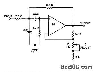
Fixed-frequency active filter gives slowly rising and falling keyed waveform with good slope considering narrowness of bandwidth, which is 75 Hz at 3 dB down. Adjusting Q with 1K pot changes bandwidth.-A.F. Stahler, An Experimental Comparison of CW Audio Filters, 73 Magazine, July 1973, p 65-70. (View)
View full Circuit Diagram | Comments | Reading(523)
TWO_STAGE_CW
Published:2009/7/2 7:33:00 Author:May
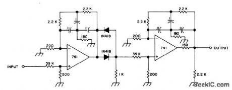
Uses diode threshold detector between stages to prevent weak undesired signals from passing through until CW signal of desired frequency is present, so as to provide quiet tuning between signals. Bandwidth of filter is sharp (16 Hz), and keyed waveform is good. Gain is near unity, and frequency and Q are both fixed.-A. F. Stahler, An Experimental Comparison of CW Audio Filters, 73 Magazine, JuIy 1973, p 65-70. (View)
View full Circuit Diagram | Comments | Reading(520)
42667_MHz_MOSFET
Published:2009/7/2 7:26:00 Author:May
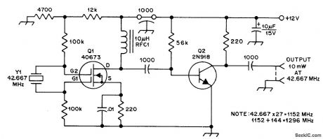
Unusual crystal-controlled oscillator, similar to modified Pierce oscillator that uses crystal between grids 1 and 2 of tetrode tube, can be used as local oscillator in VHF and UHF converters. No trimming ortuning is required to get overtone frequency. If fundamental of crystal is desired, increase RFC1 to 100 μH or replace it with 1K resistor. Stability is excellent. Circuit works well with supply as low as 4 V.-G. Tomassetti, Dual-Gate MOSFET Offers an Unusual Crystal-Controlled Oscillator Concept, QST, June 1976, p 39. (View)
View full Circuit Diagram | Comments | Reading(789)
UP_TO_30MHz
Published:2009/7/2 7:10:00 Author:May

Simple single-transistor PF oscillator is easily assembled from noncritical parts, Tuning capacitor and coil determine frequency.-Circuits, 73 Magazine, July 1977, p 35. (View)
View full Circuit Diagram | Comments | Reading(632)
GENERAL_PURPOSE_UP_TO_10_MHz
Published:2009/7/2 7:09:00 Author:May

Variation of Colpitts oscillator uses negative feedback at all frequencies at which LC network does not provide phase inversion and voltage step-up.Choose values for coil and capacitors to give frequency desired. R3 serves as regeneration control and for changing waveform of output.-G. W. Short, Good-Tempered LC Oscillator, Wire-less World, Feb. 1973, p 84. (View)
View full Circuit Diagram | Comments | Reading(651)
GATED_5_MHz_RELAXATION
Published:2009/7/2 7:03:00 Author:May
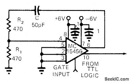
Output always startsVin same phase with respect to gating signal. Frequency-selective network R1-R2-C provides positive feedback around MC15456 gatecontrolled wideband amplifier.-F.Macli, IC Op Amp Makes Gated Oscillator, EDN Magazine,Sept. 1, 1972, p 52. (View)
View full Circuit Diagram | Comments | Reading(469)
SPIKE_REJECTlON
Published:2009/7/2 5:33:00 Author:May
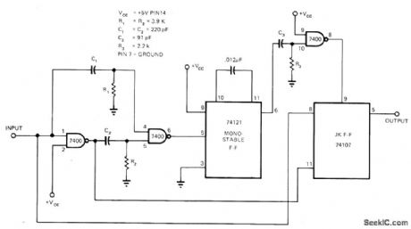
Used to eliminate noise that may be present on signal Iine. Based on sampling input Iine at fixed time after each detected transition. If transition was due to noise spike, spike will no longer be present and true signal level will be sampled. lf transition was caused by desired legitimate signal, sampled waveform represents true signal delayed by pulse width of mono MVBR. Mono pulse width is about 12μs. Article gives circuit waveforms and describes operation in detail.-A. S. Bozorth, Pulse Verification Yields Good Noise Immunity. EDN Magazine. Nov. 5. 1973. p 75 and 77. (View)
View full Circuit Diagram | Comments | Reading(637)
TTL_INrERFACE
Published:2009/7/2 5:31:00 Author:May
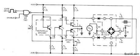
MotoroIa MPQ 6001 quad complementary-pair transistor IC serves as interface between TTL gateand diodebrldge used as signal gate. Propagation delay from leadingedge of gate drive pulse until bridge gate opens is 30 ns, with negligible delay between complementary outputs. Used in providing low-level burst of input signal when making response ime measurement.-R. W. Hilsher, Universal Interface: TTL to Diode Array, EDN Magazine, March 5, 1975, p 74 and 76, (View)
View full Circuit Diagram | Comments | Reading(580)
SCHMITT_USING_7400_GATES
Published:2009/7/2 5:20:00 Author:May
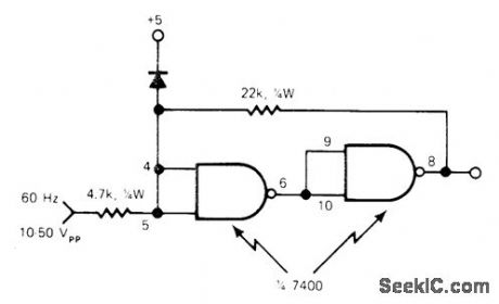
Uses two sections of 7400 quad NAND gate. Will accept input voltages of 10-50 V P-P with values shown, but can use line voltage directly if input resistor is 22K and feedback resistor is 220K. Diode in DC supply limits positive-going input to 5.7 V forprotection of input circuit. Used as interface between 60-Hz line and frequency divider having TTL logic, when 1-s time base is required for timing applications.-W. A. Palm, Connect a 7400 Gate as a Schmitt Trigger, EDN Magazine, Aug. 20, 1976, p 84. (View)
View full Circuit Diagram | Comments | Reading(745)
OR_LOGIC_FOR_MUTlNG
Published:2009/7/2 5:17:00 Author:May
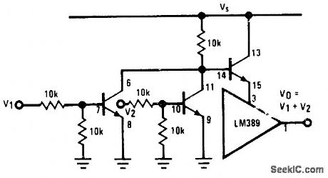
Connection shown for National LM389 combination of three transistots with opamp gives standard OR circuitfor controlling muting transistor in audio system.Shorting pin 12 of opamp to ground gives NOR logic.- Audio Handbook, National Semiconductor, Santa Clara, CA, 1977, p 4-33-4-37. (View)
View full Circuit Diagram | Comments | Reading(542)
ACTIVE_CW_FILTER
Published:2009/7/2 5:17:00 Author:May

Modifications made on MFJ Enterprises OWE-2 active audio filter per mit maximum flexibility. Circuit provides fixed bandwidth of 180 or 110 Hz centered on 750 Hz, or optional variable bandwidth for which center frequency can be adiusted in range of 280 to 1590 Hz.-H. M. Berlin, Increased Flexibility for the MFJ Enterprises CW Filters, Ham Radio, Dec. 1976, p 58-60. (View)
View full Circuit Diagram | Comments | Reading(1880)
MOS_TO_TTL_DRIVER
Published:2009/7/2 5:14:00 Author:May

National DS75450 dual peripheral driver serves as interface between different logic types while providing highspeed switching and 300-mA output current per section Requires only single 5-V supply- Interface Databook, National Semiconductor、Santa Clara,CA,1978,p3-20-3-30 (View)
View full Circuit Diagram | Comments | Reading(543)
10_kHz_VOLTAGE_TUNED_
Published:2009/7/2 5:14:00 Author:May
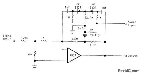
High-Q circuit using Optical Electronies 9831 opamp has sharp resonance, as required for analysis of spectrum of incoming signal. Reverse-biased silicon junctions senre as voltage variable capacitors for sweeping center frequency over 3: 1 range. Values shown for three resistors in twin-T network give cenW frequency of 10 kHz.- Voltage Tuned High-Q Filter, Optical Electronics, Tucson, AZ, Application Tip 10207. (View)
View full Circuit Diagram | Comments | Reading(599)
10_Hz_HIGH_PASS
Published:2009/7/2 5:13:00 Author:May

Equiterminated Butter-worth high-pass ladder filter has corner frequency of 10 Hz and output impedance level of 16K. Opamps are matched pair in single ML747 package. Article covers design procedure based on use of generalized impedance converters and gives frequency response curve.-L. T. Burton and D. Treleaven, Active Filter Design Using Generalized Impedance Converters, EDN Magazine,Feb. 5,1973,p 68-75. (View)
View full Circuit Diagram | Comments | Reading(1015)
THREE_LOUDSPEAKER_CROSSOVERS
Published:2009/7/2 5:12:00 Author:May

Active filter network splits AF input into three frequency bands each feeding separate 30-W power amplifier. Design allows adjustment of any part of frequency characteristic to any desired level and gives choice of slopes in any part of frequency band. Article gives design equa-tions and construction details. PNP transistors can be BCY70, BCY71, BCY72, or 2N3906. Article also gives circuit of suitable 30-W amplifier.-D. C.Read, Active Filter Crossover Networks, Wireless World, Dec.1973, p 574-576. (View)
View full Circuit Diagram | Comments | Reading(856)
60_Hz_NOTCH_FILTER
Published:2009/7/2 5:10:00 Author:May

Design is based on passband gain of 3 and O of 6. Resistors can be 5%.Opamps can be 741. Notch response is obtained by subtracting output signal of bandpass filter from its input signal whh R6.-H, M. Berlin, Design of Active Filters, with Experiments, Howard W. Sams, Indianapolis, IN, 1977, p 155. (View)
View full Circuit Diagram | Comments | Reading(2811)
HIGH_LEVEL_ACTIVATION_BY_CMOS
Published:2009/7/2 5:07:00 Author:May

High output of tpical CMOS gate drives complementary MPS-A13 Darlington transistor having80-mA lamp load.-A Pshaenich, InterfaceTechniques Between Industrial Logic and Power Devices,| Motorola,Phoenix,AZ,1975,AN-712A,p 11 (View)
View full Circuit Diagram | Comments | Reading(666)
LOGIC_PROTECTOR
Published:2009/7/2 5:00:00 Author:May
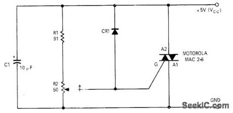
Simple bidirectional triac crowbar can be set so positive voltages above 6 V and negative voltages greater than 1.5 V cannot reach digital logic. Article covers initialadjustment of R2、-D L,Spome,Bidirectional Crowbar Protects Logic,EDN Magazine.Dec15,1970,p37 (View)
View full Circuit Diagram | Comments | Reading(541)
| Pages:290/471 At 20281282283284285286287288289290291292293294295296297298299300Under 20 |
Circuit Categories
power supply circuit
Amplifier Circuit
Basic Circuit
LED and Light Circuit
Sensor Circuit
Signal Processing
Electrical Equipment Circuit
Control Circuit
Remote Control Circuit
A/D-D/A Converter Circuit
Audio Circuit
Measuring and Test Circuit
Communication Circuit
Computer-Related Circuit
555 Circuit
Automotive Circuit
Repairing Circuit