
Basic Circuit
Index 294
THREE_DIMENSIONAL_TARGET_SIMULATOR
Published:2009/7/24 2:34:00 Author:Jessie

Trigger generator supplies zero time reference for ppi and rhi scopes and circuits of radar simulator. Course generator provides voltages proportional to X, Y, and Z target coordinates. Transformation computer with function generators converts these into polar coordinates. Range voltage from computer is compared with linear sawtooth to obtain time delay proportional to target range.-J. I. Leskinen, Four Ways lo Simulate Radar Targets, Electronics, 31:23, p 82-86. (View)
View full Circuit Diagram | Comments | Reading(602)
RAZOR_SHARP_CW_FILTER
Published:2009/7/2 2:57:00 Author:May

The circuit consists of four stages of active bandpass ftltering provided by two typeμA747 integrated-circuit dual op amps and includes a simple threshold detector (diodes D1 and D2) between stages 2 and 3 to reduce low-level background noise. Each of the four filter stages acts as a narrow bandpass ftlter with an audio bandpass centered at 750 Hz. The actual measured 3-dB bandwidth is only 80 Hz wide. (View)
View full Circuit Diagram | Comments | Reading(1964)
DIGITALLT_TUNED_LOW_POWER_ACTIVE_FILTER
Published:2009/7/2 2:53:00 Author:May

This constant gain, constant Q, variable frequency filter provides simultaneous low-pass, bandpass, and high-pass outputs with the component values shown, the center frequency will be 235 Hz and 23.5 Hz for high and low logic inputs respectively; Q = 100, and gain = 100. (View)
View full Circuit Diagram | Comments | Reading(754)
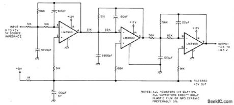
ACTIVE_LOW_PASS_FILTER_WITH_DIGITALLY_SELECTED_BREAK_FREQUENCY
Published:2009/7/2 2:50:00 Author:May


Variable low-pass ftlter has break frequencies at1, 10, 100 Hz and 1 kHz. The break frequency isThe low frequency gain isA second break frequency(a zero)is introduced by rDS(on )of the DG201A,causing theminimum gain to bea maximum attenuation of 40 dB (80 dB relative to the low frequency gain)。 (View)
View full Circuit Diagram | Comments | Reading(825)
0-5000_Hz_WHITE_NOlSE
Published:2009/7/2 2:30:00 Author:May
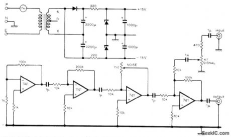
Both signal and noise levels are continuously and independently variable from zero to maximum in simple noise generator developed to demonstrate recovery of low-level 500.Hz signal from noise. Circuit gives maximum noise output into 1500-ohm load; for lower load impedances, reduce noise level to prevent oscillation. Opamps require±15 V supply.Which can be simple voltage doubler with regulation,-J.E.Morris.Simple Noise Generator.Wireless world.April 1977.p 62. (View)
View full Circuit Diagram | Comments | Reading(718)
WIDEBAND_TWO_POLE_HIGH_PASS_FILTER
Published:2009/7/2 2:26:00 Author:May

The circuit provides a 10MHz cutoff frequency.Resistor R3 ensures that the tnputcapacitance of the amplifier does not interact with the filter response at the frequencyof interest.An equivalent low pass filter is similarly obtained by capacitance and resistance transformation (View)
View full Circuit Diagram | Comments | Reading(0)
LOW_COST_UNIVERSAL_ACTIVE_FILTER
Published:2009/7/2 2:18:00 Author:May


The circuit as shown in Fig. 1 gives the bandpass operation the transfer function calculated from
Interchanging the capacitor C with the resistor R at the input of the circuit high-pass operation is obtained. A low-pass filter is obtained by applying two parallel connections of R and C as shown in Fig. 2.
The low-pass operation may be much improvedwith the circuit as gtven h Fig.3.Here the gamand Q may be set up separately with respectto the cut-off frequency according to theequations (View)
View full Circuit Diagram | Comments | Reading(847)
LIGHT_TRANSMISSION_CHECKER
Published:2009/7/2 2:16:00 Author:May
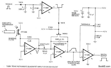
Phototransistor and quad opamp serve as total-energy detector of pulsed-light signals propagated through fiber-optic cable of communication system. Can be used for checking and comparing condition of long fibers if light intensity of source is held constant. Will also detect changes in light intensity and changes in pulse width. Circuit gives linear response to light levels from 100 to 10,000 ergs/cm2 if minimum pulse width is at least10 μs. A2, acts as RC integrator, giving voltage proportional to total light energy received. A4 provides comparison to fixed level.-E. W. Rummel, Low-Level-Light Detector Checks Optical Cables Fast, Electron-Jcs, April 27, 1978, p 148 and 150.
(View)
View full Circuit Diagram | Comments | Reading(1248)
IF_NOISE_BLANKER
Published:2009/7/2 2:15:00 Author:May
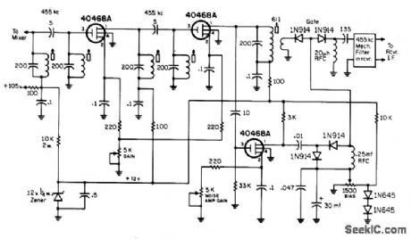
Used ahead of 455.kHz IF strip of communication receiver to provide about 40-dB attenuation of ignition and other noise pulses that can interfere with reception in 2- and 6-meter amateur bands. Two paths for noise pulses, one AC and the other DC, must be balanced for good operation. Resistor and capadtor values in noise rectifier are chosen to select sharp noise pulses in preference to signals. DC noise pulses are amplified by pulse amplifier and converted to AC notse pulses. Settings of pots are optimized for best noise blanking. Circuit requires 12-V supply, which can be obtained from receiver with appropriate dropping resistors and zener as shown for +105 V, or from separate source.-F. C. Uones. Ex. perimental I.F. Noise Blankers, CQ, March 1971, p81-83. (View)
View full Circuit Diagram | Comments | Reading(2366)
24_MEGABIT_DATA_LINK
Published:2009/7/2 2:07:00 Author:May
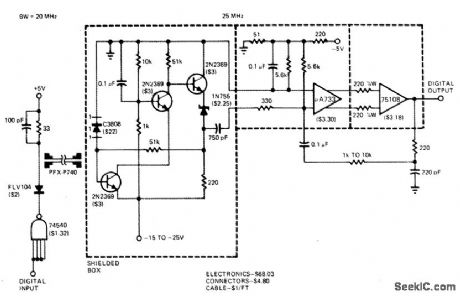
High data-rate capability for square-wave pulses is achieved by increasing complexity of receiver feeding digital output to microprocessor from remote teleprinter. Preamp design compensates for noise over limited frequency range, giving uniform S/ N ratio to about 20 MHz. With demonstration setup, visible-spectrum LED and photodetector shown performed acceptably with 40-foot cable.-O. E. Malvel and J. C. Freeborn, A Little Hands-On Experience llluminates Fiber-Optic Links, EDN Magazine, Nov. 5, 1977, p 71-75. (View)
View full Circuit Diagram | Comments | Reading(530)
AM_NOISE_SILENCER
Published:2009/7/2 2:02:00 Author:May

Circuit samples mixer output (IF input) of AM receiver and, when noise pulse is detected, interrupts IF input signal for duration of noise pulse. Uses National LM372IC having AGC loop with range of about 69 dB, for accommodating wide range of input levels. Artide describes operation of circuit in detail. For frequencies above 2 MHz, use LM373 in place of LM372.-T. A. Tong, Noise Silencer torA.M. Receivers, Wireless World. Oct. 1972. p 483-484. (View)
View full Circuit Diagram | Comments | Reading(963)
THEREMIN
Published:2009/7/2 1:40:00 Author:May

Two transistor oscillator stages generate separate low-power RF signal in broadcast band, for pickup by AM broadcast receiver. Movement of hand toward or away from metal pitch plate varies trequency of Q1, making audio output of receiver vary conespondingly as beat frequency changes. Both circuits are Hartley oscillators, using Miner 9012 or equivalent slug-tuned colls. To adjust initially, place next to radio and set tuning slug of L1 about two-thirds out of its winding. Set slug of L2 about one-third out of its winding. Tune radio until either oscillator signal is heard. Signal can be identified by whistle if on top of broadcast station or by quieting of background noise if between stations. Adjust slugs so whistle is heard at desired location ot quieting signal. Pitch of whistleshould change now ashand is brought near pitch plate.-J. P Shields, How to Build Proximity Detectors & Metal Locators, Howard W. Sams, Indianapolis, IN, 2nd Ed. 1972. p 154-156. (View)
View full Circuit Diagram | Comments | Reading(2953)
HAND_WAVING_THEREMIN
Published:2009/7/2 1:31:00 Author:May
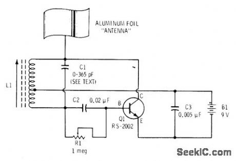
Single-transistor RF oscillator is tuned to generate frequency about 455 kHz above oscillator frequency of transistor radio. With aluminum-foil antenna away from nearby objects and radio tuned be-tween stations, R1 is adjusted until highpitched tone is heard from radio. Now, as hand is brought toward and away from foil antenna, wailing sounds are produced. With practice, musician can produce recognizable melodies by vibrating hand. Primary controls of frequency are C1 (10-365 pF broadcast radio tuning capacitor) and adjustable antenna coil L1 (Radio Shack 270-1430). Radio can be up to 15 feet away from theremin. Rotate radio for maximum pickup from L1-F. M. Mims, Electronic Music Projects, Vol. 1, Radio Shack, Fort Worth, TX, 1977, 2nd Ed. p 81-89. (View)
View full Circuit Diagram | Comments | Reading(1623)
FOUR_OCTAVE_ORGAN
Published:2009/7/2 1:06:00 Author:May
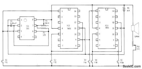
Two 7473 dual flipflops provide four frequency dividers for 555 timer connected as master tone generator. S1 gives fundamental frequency. and each succeedlig switch gives tones precisely one octave lower. Four organ applications, pushbutton switches are added to timer circuit for switching frequency-controlling capacitors or resistors to give desired variety of notes.-F. M. Mims.″Electronic Music Proiects.vol 1.″Radio Shack.Fod Wodh.TX.1977.2nd Ed.p45-53. (View)
View full Circuit Diagram | Comments | Reading(2059)
ATTACK_DECAY_GENERATOR
Published:2009/7/2 0:58:00 Author:May
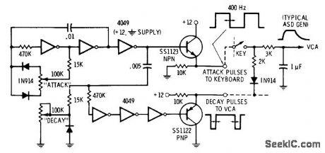
Designed for polytonic electronic music system handling more than one note at a time. Each note to be controlled is sent through voltage-controlled amplifier (VCA) whose gain is set by charge on capacitor. Attack is changed by varying charging rate. Discharge rate sets decay of individual note. To avoid having separate adjustment pot for each VCA, duty-cycle modulation is used to change charging current through resistors. Attack pulses are generated by upper three inverters forming variable-symmetry astable MVBR. Decay pulses are generated by lower three inverters connected as half-mono MVBR.
Additional half-monos can be added as needed for percussion, snubbing, and other two-step decay effects.-D. Lancaster, CM0S Cook-book.''Howard W.Sams.Indianapolis.IN.1977.p231-232 (View)
View full Circuit Diagram | Comments | Reading(679)
450_500_kHz_WOBBULATOR
Published:2009/7/2 0:54:00 Author:May
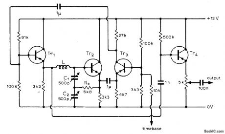
Center frequency of sweep is adjusted with C1 and C2. With appropriate coil, operation can be extended up to 10.7 MHz. Transistors can be BC107, BF115, BF194, or other equivalent. Choose value of Rx to give best waveform with transistor types used. Feedback for VCO is taken via Tr3 without phase change. If control voltage for base of Tr3 is derived from ramp out-put of oscilloscope time base, wobbulator out-put will follow variations in sweep voltage of time base.-E. C. Lay, Wobbulator, Wireless World, May 1975, p 226. (View)
View full Circuit Diagram | Comments | Reading(2884)
SECONDARY_STANDARD_FOR_100_AND_10_kHz
Published:2009/7/2 0:52:00 Author:May
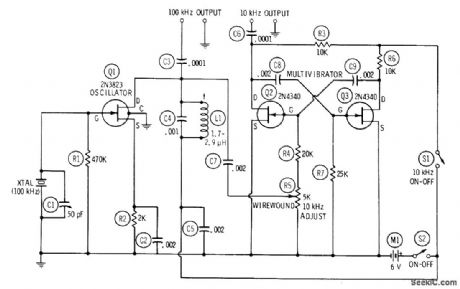
Combination of 100-kHz crystal oscillator and 10-kHz MVBR provides 100-kHz harmonics far up into high-frequency spectrum, with each 100-kHz interval subdivided by harmonics of MVBR using two FETs. Oscillator is tuned to crystal frequency whh Miller 42A223CBl or equivalent slug-tuned coil L1. C1 ad justs crystal frequency over narrow range for standardizipg against WWV transmissions. Synchronizing 100-kHz voltage is injected into MVBR through R5.-R. P. Turner, FET Circuits, Howard W. Sams, Indianapolis, IN, 1977, 2nd Ed., p 127-129. (View)
View full Circuit Diagram | Comments | Reading(906)
LOW_PASS_WITH_3_kHz_CUTOFF
Published:2009/7/2 0:51:00 Author:May
Used in computer music system to suppress high-fidelity distortion resulting from steps in sine-wave output of DAC. Article covers complete computer synthesis of music by microprocessor and gives frequency table. program for generating four simultaneous musical voices, and song table for encoding The Star Spangled Banner in four-part harmony, using 5 bytes per musical event.-H. Chamberlin,A Sampling of Techniques for Computer Performance of MusiC.BYTE.Sept.1977.p62-66.68-70.72.74.76-80.and 82-83. (View)
View full Circuit Diagram | Comments | Reading(536)
ATTACK_DECAY
Published:2009/7/2 0:46:00 Author:May
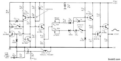
Waveform generator produces approximate rectangular waveform having exponential rise (attack) and exponential decay, initiated either by manual trigger or electronic signal derived from other circuits of sound synthesizer. All characteristics of waveform are arbitrarily variable. Three-part article describes circuit operation and gives all other circuits used in synthesizer for generating wide variety of musical and other sounds-T Orr and D W Thomas.Electronic Sound Syntheslzer.Wireless World,Part 3-Oct 1973.p485-490(Part 1-Aug .1973、 p 366-372; Part 2-Sept 1973.p 429-434) (View)
View full Circuit Diagram | Comments | Reading(1352)
TROMBONE_CIRCUIT
Published:2009/7/2 0:42:00 Author:May
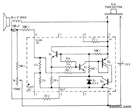
Unique arrangement for driving 25-ohm loudspeaker with National LM3909 IC operating from 1.5-V cell permits generation of slide tones resembling those of trombone. Operation is based on use of voltage generated by resonant motion of loudspeaker voice coil as major positive feedback for IC. Loudspeaker is mounted in roughly cubical box having volume of about 64 in, with one end of box arranged to slide in and out like piston. Positioning of piston and operation of pushbutton permit playing reasonable semblance of simple 15 V tune. IC, loudspeaker, and battery are mounted on piston, with 2 1/2-in length of 5/16-in tubing provided to bleed air in and out as piston is moved, without affecting resonant frequency. Frequency of oscillator becomes equal to resonant frequency of enclosure.- Linear Applications, Vol. 2, National Semiconductor, Santa Clara, CA, 1976, AN-154, p 6. (View)
View full Circuit Diagram | Comments | Reading(555)
| Pages:294/471 At 20281282283284285286287288289290291292293294295296297298299300Under 20 |
Circuit Categories
power supply circuit
Amplifier Circuit
Basic Circuit
LED and Light Circuit
Sensor Circuit
Signal Processing
Electrical Equipment Circuit
Control Circuit
Remote Control Circuit
A/D-D/A Converter Circuit
Audio Circuit
Measuring and Test Circuit
Communication Circuit
Computer-Related Circuit
555 Circuit
Automotive Circuit
Repairing Circuit