
Basic Circuit
Index 286
DARLINGTON_LOGIC_PROBE
Published:2009/7/2 22:01:00 Author:May

Two-transistor Darlington connection provides very high input impedance that does not load logic circuit being monitored, while driving LED that glows when logic 1 is present at input.-F. M. Mims, Computer Circuits for Experimenters, Radio Shack, Fort Worth, TX, 1974, p 35-43. (View)
View full Circuit Diagram | Comments | Reading(1793)
BUILT_IN_LOGIC_PROBE
Published:2009/7/2 21:58:00 Author:May
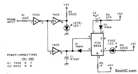
PROBE-Permanently wired LEDs indicate TTL levels and changes in levels, LEVEL LED-1 comes on for TTL 1 input and goes out for TTL 0 input. EDGE LED-2 comes on momentarily for input changes. Will detect levels, steps, single pulses, and pulse trains. Only haif of each IC is used, so dual tester can be made if desired. ICs 1a and 1b form noninverting driver for 9602 mono which is triggered on both positive-going and negative-going edges by C1 and D1. Pulse train input having period less than width of flash pulse will keep EDGE indicator on.-K. W. Christner, The Built-In Logic Tester, BYTE, Jan. 1977, p 82-83. (View)
View full Circuit Diagram | Comments | Reading(506)
1_kHz_THREE_FUNCTION
Published:2009/7/2 21:50:00 Author:May
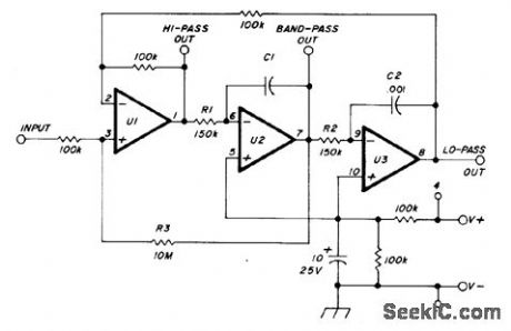
Uses National LM324 quad opamp, with appropriate biasing for single supply of +5 to +25 VDC. Values of R1 and R2 establish fc at 1000 Hz, while R3 gives Q of 50. Values of R1 and R2 for other bandpass center and cutoff frequencies fc can be calculated from R = 15 ×107/fc. Fourth opamp may be used as output amplifier or for summing highpass and low-pass outputs. C1 is same as C2.-P. A. Lovelock, Discrete Operational Amplifier Active Filters, Ham Radio, Feb. 1978, p 70-73. (View)
View full Circuit Diagram | Comments | Reading(651)
LOGIC_PROBE
Published:2009/7/2 21:49:00 Author:May

Pocket-size battery-powered probe using two inexpensive CMOS ICs has such low standby current drain that ON/OFF switch is unnecessary. Drain is appreciable only when LEDs are on during use. Mallory TR-133 4.2-V mercury battery gives 2-V threshold for TTL compatibility. LEDs come on to indicate logic 1. Pulse-stretching circuit ensures detecting positive or negative pulses as short as 250 ns.-J. Edrington, Battery-Powered Logic Probe Needs No ON/OFF Switch, EDN Magazine, May 20, 1975, p 72 and 74. (View)
View full Circuit Diagram | Comments | Reading(0)
19_kHz_NOTCH
Published:2009/7/2 21:48:00 Author:May
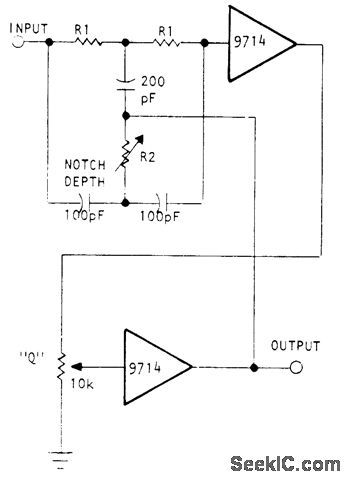
Used in commercial FM transmitters to eliminate 19-kHz program material from stereo encoder. Uses Optical Electronics 9714 opamp in circuit that gives unity passband gain below center frequency, 0.7 gain above center frequency, and Iess than 0.001 gain at notch frequency. Provides adjustments for notch rejection level and Q. R1 is 84K, and R2 is 36K in series with 10K pot.- Precision Notch Filter, Optical Electronics, Tucson, AZ, Application Tip 10255. (View)
View full Circuit Diagram | Comments | Reading(652)
1_kHz_CASCADED_OPAMP_BANDPASS
Published:2009/7/2 21:47:00 Author:May
Bandwidth of only 71 Hz is achieved by using four identical three-opamp filters in series, for increased selectivity in communication or RTTY receiver. Values for R1 and R2 are made variable for first filter stage, but pot is used for R3 in all four stages so they can betuned to same center frequency. Batteries are used for supply, asfilter draws only 17 mA.-F. M. Griffee, RC Active Filters Using Op Amps, Ham Radio, Oct. 1976, p 54-58. (View)
View full Circuit Diagram | Comments | Reading(444)
RTL_TTL_PROBE
Published:2009/7/2 21:46:00 Author:May
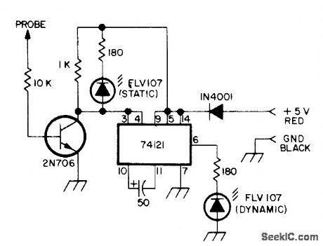
Static LED indicates logic Ievel at probe tip. Dynamic LED indicates presence of high or 1 pulse at probe tip even though momentary, because circuit stretches pulse to about 50 μs for easy visibility. Pulse stretcher requires at least 100-ns 4-V pulse. 1N4001 diode protects against reversed power leads. Probe requires +5 V from circuit under test. LEDs and transistor are not criticaL-Circuits, 73 Magazine, April 1974, p 31. (View)
View full Circuit Diagram | Comments | Reading(621)
HALF_WAVE_RECTIFIER
Published:2009/7/2 21:43:00 Author:May

Provides accurate half-wave rectification of incoming signal. Gain is 0 for positive signals and -1 for negative signals. Diodetypes are not critical. Polarity can be inverted by reversing both diodes. With opamp shown, circuit will function up to 10 kHz with less than 5% distortion.- Sig netics Analog Data Manual. Signetics. Sunnyvale. CA. 1977. p 641-643. (View)
View full Circuit Diagram | Comments | Reading(2948)
LOGIC_STATE_PROBE
Published:2009/7/2 21:41:00 Author:May
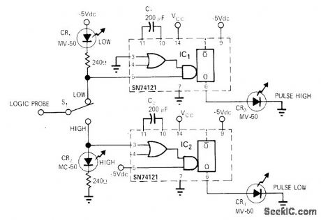
Useful for low-repetition-rate applications having single narrow pulses, as in computer interfaces and logic control systems. Pulses as narrow as 50 ns are stretched by mono so they provide LED indication. If teady state of circuit under test is low, CR1 will light when S1 is in in low position. If steady state is high, CR2 will light when switch is high. Other two lamps indicate presence of pulse superimposed on steady-state signal. If repetition frequency of pulse is high, pulse light Speed Logic Probe, EDNlEEEMagazine, Nov. 1,1971, p 51. (View)
View full Circuit Diagram | Comments | Reading(817)
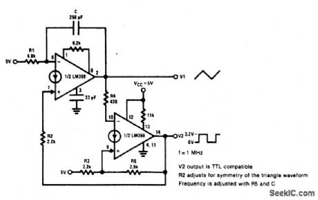
TRIAGLE_AND_SQUARE_WAVEFORM_GENERATOR
Published:2009/7/2 21:39:00 Author:May
View full Circuit Diagram | Comments | Reading(490)
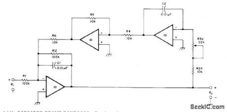
SIGNAL_SEPARATOR
Published:2009/7/2 21:37:00 Author:May

Circuit shown for Harris HA-2530 opamp separates input voltage into its positive and negative components. Diodes steer components to separate outputs. Appli-cations include feeding outputs into differential amplifier to produce absolute-value circuit for multiplying or averaging functions. For bandwidth of 1 MHz. dynamic range is 100 mV to 10 V peak.- Linear & Data Acquisition Products.}| Harris Semiconductor. Melbourne. FL. Vol. 1. 1977. p 7-54-7-55 (Application Note 516). (View)
View full Circuit Diagram | Comments | Reading(669)
LOW_PASS_WITH_10_kHz_CUTOFF
Published:2009/7/2 21:24:00 Author:May

Simple circult uses only one Texas Instruments SN72310 voitage-fonower opamp,For good temperature stability,use silvered mlca capacitors.- TheLinear and Interface Circuits Data Book for Design Engineers, Texas Instruments,Danas,TX,1973,p 4-39. (View)
View full Circuit Diagram | Comments | Reading(586)
CLOCK_FOR_COMMUTATING_RC_FILTER
Published:2009/7/2 21:22:00 Author:May

Circuit synchronizes multivibrator with line frequency to provide dock waveform required for switching capacitors electronically in npath active filter for rejecting line frequency and harmonics up to fifth. Article gives complete circuit of active filter and describes operation. Clock serves to switch 16 MOSFETs on in turn for commutating 16 capacitors electronically at 16 times line frequency.-K. F. Knott and L. Unsworth, Mains Rejection Tracking Filter, Wireless World, Oct. 1974, p 375-379. (View)
View full Circuit Diagram | Comments | Reading(662)
LOGIC_PROBE
Published:2009/7/2 21:21:00 Author:May

Provides almost as much information, when working with TTL or DTL digital circuits, as costly CRO or logic analyzer. Can be built into length of plastic tubing, with probe tip projecting at one end and two supply leads coming from other end.One LED flashes for high to low transition, and other for low to high transition. Flash is visible even with very narrow pulses, because probe circuit stretches pulse width. With S1 open (memory mode), pulse LED at right stays on until reset by operator, for capturing any stray pulse. If probe tip is held on open circuit or on chain of floating inputs, no LED will light.-C. W. Andreasen, Superprobe, 73 Magazine, Holiday issue 1976, p 92-93. (View)
View full Circuit Diagram | Comments | Reading(2944)
60_Hz_HIGH_Q_NOTCH
Published:2009/7/2 21:19:00 Author:May
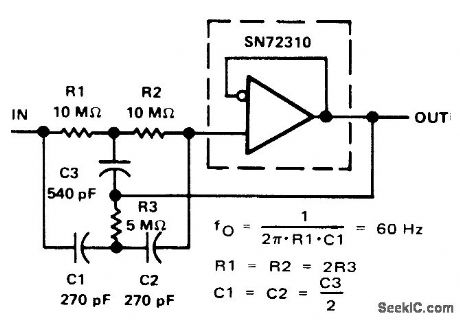
Input network for SN72310 voltage-follower opamp provides at-tenuation of 60-Hz power-line frequency. Use high-quality capacitors for maximum a.- The Linear and Interface Circuits Data Book for Design Engineers, Texas Instruments, Dallas, TX, 1973, p 4-39. (View)
View full Circuit Diagram | Comments | Reading(592)
FET_LOGIC_PROBE
Published:2009/7/2 21:15:00 Author:May
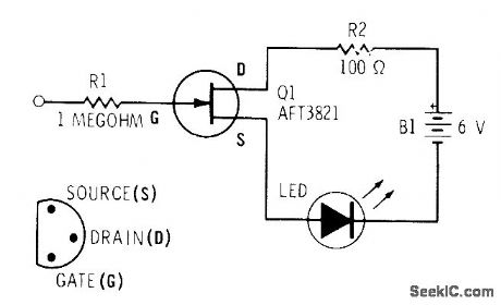
Field-effect transistor with very high input resistance makes LED glow when logic 1 is present at input, without loading circuit being monitored.-F. M. Mints, Computer Circuits for Experimenters, Radio Shack, Fort Worth, TX, 1974, p 35-43. (View)
View full Circuit Diagram | Comments | Reading(655)
FASTER_741
Published:2009/7/2 21:14:00 Author:May

Feed-forward techniques extend dynamic response of differential opamp to give unity-gain bandwidth of 18MHz, slew rate over 200 V/μs, and DC gain above 107 V/V while preserving latchup-free operation and wide input voltage range. Composite amplifier uses fast symmetrical four-transistor output stage that is symmetdcally driven by DC-coupled 741 and by AC-coupled feed-forward amplifier, Performance depends on use of nonstandard pin connections for 741. as shown. Developed for processing fast analog data in frequency domain. -J Dostal. 741 + Feedforward =Fast-Differential Op Amp EDN Magazine. Aug 20.1974.p 90. (View)
View full Circuit Diagram | Comments | Reading(925)
TTL_STATE_PROBE
Published:2009/7/2 21:13:00 Author:May
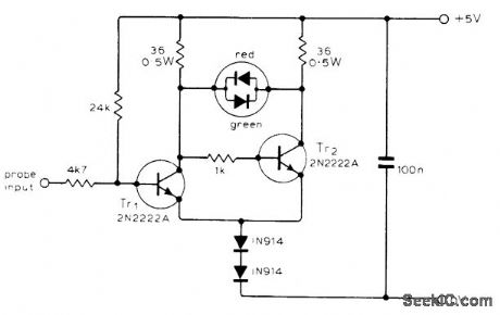
Uses voltage drop of LED in Schmitt trigger to indicate high, low, opencircuit, and pulse-train conditions at probe input. Indicator is Monsanto MV5491 dual redgreen LED package. High input saturates Tr1, cuts off Tr2, and turns on red LED. Low inputcuts off Tr1, and turns on green LED. For high impedance at input, both LEDs are off. Rectangular waves up to about 1 MHz turn on both LEDs, with relative brightness giving rough indication of mark-space ratio.-J. C. Flower, Logic Probe, Wireless World, Sept. 1976, p 72. (View)
View full Circuit Diagram | Comments | Reading(690)
1_Hz_BANDPASS
Published:2009/7/2 21:13:00 Author:May

Single pot provides easy trimming to exact center frequency desired without change in bandwidth or gain. Q is 10.Design equations are given.-R. A. Pease, Band-Pass Active Filter with Easy Trim for Center Frequency, Teledyne PhilbHck, Dedham, MA, 1972, Applications Bulletin 4. (View)
View full Circuit Diagram | Comments | Reading(734)
1_kHz_BANDPASS_1
Published:2009/7/2 21:11:00 Author:May

Simple circuit using voltage-fonower opamp provbides bandpass of 1 kHz centered on 1 kHz,to give outputrange of 500-1500 Hz.- The Linear and Interface Circuits Data Book for Design Engineers, Texas Instruments, Dallas, TX, 1973, p 4-39. (View)
View full Circuit Diagram | Comments | Reading(558)
| Pages:286/471 At 20281282283284285286287288289290291292293294295296297298299300Under 20 |
Circuit Categories
power supply circuit
Amplifier Circuit
Basic Circuit
LED and Light Circuit
Sensor Circuit
Signal Processing
Electrical Equipment Circuit
Control Circuit
Remote Control Circuit
A/D-D/A Converter Circuit
Audio Circuit
Measuring and Test Circuit
Communication Circuit
Computer-Related Circuit
555 Circuit
Automotive Circuit
Repairing Circuit