
Basic Circuit
Index 283
EKG_FM_DEMODULATOR
Published:2009/7/3 2:23:00 Author:May
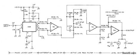


Devel oped as part of system using satellitefor relaying electrocardiograms and other medical data having bandwidth of 0.5 to 50 Hz. Audio signal serving as source of FM is applied to voltage-controlled 1-kHz oscillator having ±40% deviation for fullscale input. Corresponding audio signal at receiving location is fed to input of 565 phaselocked loop. Error voltage of loop, at pin 7, conitains data being sought as well as undesirable DC and AC components. DC component of error signal is removed by 741 differential amplifier following PLL. Following four-pole active RC low-pass filter eliminates high-frequency AC components and determines bandwidth of demodulator. Cutoff frequency is 100 Hz. Final 741 opamp scales and shifts output to reasonable value. Recorded output could not be distinguished from original EKG by doctors.-D. Nelson, Medical Data Relay via Oscar Satellite, Ham Radio, April 1977, p 67-73. (View)
View full Circuit Diagram | Comments | Reading(2471)
INCREASING_THE_POWER_RATING_OF_ZENER_DIODES
Published:2009/7/3 2:21:00 Author:May
Circuit Notes
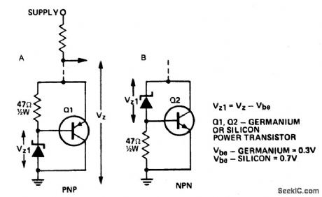
A power transistor can be used to provide a high powered zener voltage from a low wattage zener. A 400 mW zener can be used where a 10 watt zener is required or a 1W zener cait be used where a 50 to 80 watt zener is required by using appropriate transistors for Q1 and Q2 in the circuits shown. Where low rating is required, Q1 would be an ASZ 15 (germanium) or an AY9140 (silicon). Q2 could be a 2N2955 (silicon). For higher powers, Q1 should be an ASZ18 (germanium) or a 2N2955 (silicon) and Q2 a 2N3055 (silicon) or an AY8149 (silicon). A heatsink on the transistor is required. The circuit in A has the advantage that power transistors can be bolted directly on to a chassis which may serve as a heatsink. (View)
View full Circuit Diagram | Comments | Reading(2751)
AF_LOW_PASS_FOR_CW
Published:2009/7/3 2:20:00 Author:May

Design using 10% tolerance components gives sufficiently wide bandwidth while maintaining steep skirt re sponse for CW reception in direct-conversion communication receiver. Filter has five identical three-transistor sections, each peaked at cutoff frequency. a of each section is about 1.9, which gives 6-dB bandwidth of about 200 Hz. With center frequency at 540 Hz attenuation is 75 dB at 1200 Hz. Net gain of system is 28 dB at resonance. NPN transistors are 2N3565,2N3904, or similar; PNP transistors are 2N3638, 2N3906, or similar.-W. Howard, Simple Active Filters for Direct-Conversion Receivers, Ham Radio, April 1974, p 12-15. (View)
View full Circuit Diagram | Comments | Reading(989)
TUNABLE_FOURTH_ORDER_LOW_PASS
Published:2009/7/3 2:19:00 Author:May

Use of four ganged pots permits varying cutoff frequency over 10:1 range. Table gives ranges obtainable with five different values for C.Opamps can be 741 or equivalent. Tracking of 5% for pots calls for expensive components, but ordinary snap-together pots may prove satisfactory if tuning range is restricted to 3:1 or less and more capacitor switching is used.-D. Lancas.ter, Active-Filter Cookbook, Howard W.Sams,Indianapolis, IN, 1975, p 195-197. (View)
View full Circuit Diagram | Comments | Reading(736)
24_kHz_LOW_PASS_HIGH_PASS
Published:2009/7/3 2:18:00 Author:May

Three 741 opamps are connected toprovide separate low-pass and high-pass outputs simultaneously for complex synthesis problem requirIng state-variable filter Gain is 1.-D,Lancaster, Active-Filter Cookbook, Howard W,Sams,Indianapolis,IN,1975, p 192-193. (View)
View full Circuit Diagram | Comments | Reading(774)
1_kHz_HIGH_PASS_FLATTEST_RESPONSE
Published:2009/7/3 2:17:00 Author:May

Values are chosen for flattest possible response obtainable with third-order configuration of two 741 opamps. Tripling capacitance values cuts cutoff frequency by one-third and vice versa. Component tolerance can be 10%. Gain is 2.-D.Lancaster, Active-Filter Cookbook, Howard W. Sams, Indianapolis, IN, 1975, p 186. (View)
View full Circuit Diagram | Comments | Reading(497)
ZENER_DIODE_INCREASE_FIXED_PNP_REGULATOR’S_OUTPUT_VOLTAGE_RATINGS
Published:2009/7/3 2:12:00 Author:May

Circuit Notes
A zener diode in the ground lead of a fixed pnp regulator varies the voltage output of that device without a signiftcant sacriftce in regulation. The technique also allows the regulator to operate with output voltages beyond its rated limit. (View)
View full Circuit Diagram | Comments | Reading(930)
225_MHz_FRONT_END_
Published:2009/7/3 2:11:00 Author:May
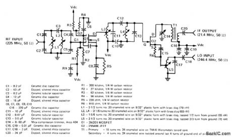
RF stage, mixer, and tuned circuits are designed for use in FM communication receiver having local oscillator input of 246.4 MHz, for IF of 21.4 MHz .Supply voltage is 12.5 V. Spurious-response rejecti is 100 dB, image rejection is 97 dB, and noise figure is 12 dB.-J. Hatchett and B. Morgan, Economical 225 MHz Receiver Front End Em ploys FETs, Motorola, Phoenix, AZ, 1978, EB22. (View)
View full Circuit Diagram | Comments | Reading(1641)
SENSING_MUSCLE_TENSION
Published:2009/7/3 1:55:00 Author:May
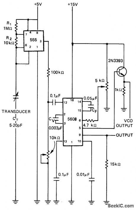
Capacitive transducer of type used for measuring displacement and pressure is used to modulate 555 MVBR. Frequency is detected in NE560B PLL that produces DC output voltage. CF sets bandwidth of demodulated information. Zero-position frequency of transducer is measured at pin 12 of PLL, and VCO frequency of PLL is measured from pin 5 through 2N3393 emitter-follower stage.-R. M. Wise, Capacitive Transducer Senses Tension in Muscle Fibers, Electronics, June 26, 1975, p 97; reprinted in Circuits for Electronics Engineers, Electronics, 1977, p 349. (View)
View full Circuit Diagram | Comments | Reading(607)
LINE_FM_DEMODULATOR
Published:2009/7/3 1:50:00 Author:May

Exar XR-2212 predsion PLL IC provides Iinear demodulation for both narrow-band and wideband FM signals. Article gives circuit design procedure.With +12 V supply voltage and 67-kHz carrier frequency having ±5 kHz frequency deviation, R0 is 18K fixed resistor in series with 5K pot. C0 (between pins 13 and 14) is 746 pF, R1 is 89.3K, C1 is 186 pF, RF is 100K, and RC is 80.6K. These values give ±4 V P output swing. AII values except R0 can be lounded off to nearest standard value.- Phase-Locked Loop Data Book, Exar Integrated Systems, Sunnyvale, CA, 1978, p 35-40. (View)
View full Circuit Diagram | Comments | Reading(1943)
OFF_LINE_FLYBACK_REGULATOR
Published:2009/7/3 1:47:00 Author:May
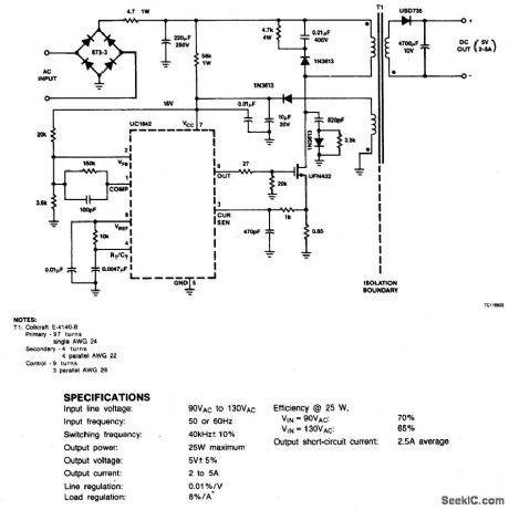
Circuit NotesThis circuit uses a low-cost feedback scheme in which the dc voltage developed from the primary-side control winding is sensed by the UC1842 error amplifier. Load regulation is therefore dependent on the coupling between secondary and control windings, and on transformer leakage inductance. For applications requiring better load regulation, a UC1901 Isolated Feedback Generator can be used to directly sense the output voltage. (View)
View full Circuit Diagram | Comments | Reading(1096)
FM_DEMODULATOR_1_
Published:2009/7/3 1:44:00 Author:May
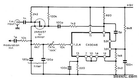
Uses RCA CA3046 IC IF amplifier connected as highly linear voltage-controlled oscillator, in phase-locked loop configuration capableof handling 10.7-MHz amplitude-limited FM input as FM demodulator.Output AF signal is about 20 mV for 75-kHz deviation. FET serves as synchronouschopper type of phase-sensitive detector.-J. L. Linsley Hood, Linear Voltage Controlled Oscillator, Wireless World, Nov. 1973, p 567-569. (View)
View full Circuit Diagram | Comments | Reading(2845)
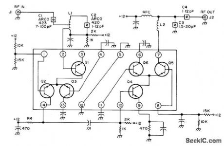
ACTIVE_ANTENNA_1
Published:2009/7/3 0:01:00 Author:May
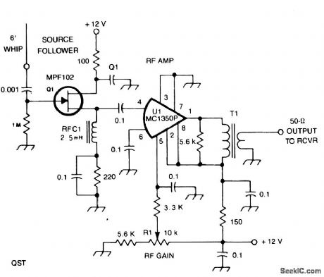


All capacitors in this circuit are disc ceramic.Fixed-value resistors are 1/4- or 1/2-W carbon. R1 controls the gain of U1. RFC1 is a miniature 2.5-mH rf choke. T1 has 30 primary turns of #28 enamel wire on an Amidon FT50 -43 ferrite toroid core, and the secondary has four turns of #28 wire. (View)
View full Circuit Diagram | Comments | Reading(752)
ACTIVE_ANTENNA
Published:2009/7/2 23:55:00 Author:May

Antennas that are much shorter than 1/4 wavelength present a very small and highly relative impedance that is dependent on the received frequency. It is difftcult to match impedances over a decade of frequency coverage. Instead, input stage Q1 is an FET source-follower. A high-impedance input successfully bridges antenna characteristics at any frequency.Transistor Q2 is used as an emitter-follower to provide a high-impedance load for Q1, but more importantly, it provides a low-drive impedance for common-emitter amplifter Q3, which provides all of the amplifter's voltage gain. Transistor Q4 transforms Q3's moderate output impedance into low impedance, thereby providing sufftcient drive for a receiver's 50-Ω, antenna-input impedance. (View)
View full Circuit Diagram | Comments | Reading(2229)
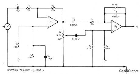
2258_Hz_REJECTION
Published:2009/7/2 23:45:00 Author:May

Provides extremely sharp adjustable-depth notch with only two low-gain opamps. Suitable for single-ended supplies. Article gives equation for transfer function.-R. Carter, Sharp Null Filter Utilizes Minimum Component Count, EDN Magazine, Sept. 20, 1976, p 110.
(View)
View full Circuit Diagram | Comments | Reading(578)
100_kHz_LOW_PASS_UNITY_GAIN
Published:2009/7/2 23:45:00 Author:May
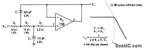
Opamp serves as active element in voltage-controlled voltage-source second-order filter. Other opamps having required high input resistance, low input current, and high speed are 1556 and 8007.-W. G. Jung, IC Op-Amp Cookbook, Howard W. Sams, Indianapolis, IN, 1974, p 331-333. (View)
View full Circuit Diagram | Comments | Reading(507)
VARIABLE_Q_AND_FREQUENCY_1
Published:2009/7/2 23:43:00 Author:May

Bandwidth can be made extremely sharp (less than 9 Hz) or very broad (greaterthan 300 Hz) Adiusting Q to change bandwidth also changes gain of filter.Center frequency of filter is independently adjustable.-A. F. Stahler, An Experimental Comparison of CW Audio Filters, 73 Magazine, July 1973, p 65-70. (View)
View full Circuit Diagram | Comments | Reading(716)
VARIABLE_Q_AND_FREQUENCY
Published:2009/7/2 23:42:00 Author:May
Bandwidth can be made extremely sharp (less than 9 Hz) or very broad (greaterthan 300 Hz) Adiusting Q to change bandwidth also changes gain of filter.Center frequency of filter is independently adjustable.-A. F. Stahler, An Experimental Comparison of CW Audio Filters, 73 Magazine, July 1973, p 65-70. (View)
View full Circuit Diagram | Comments | Reading(595)
3_kHz_STATE
Published:2009/7/2 23:42:00 Author:May

VARIABLE BANDPASS-Design is based on value of 30 for Q, corresponding to 0.033 for damping factor d. Opamps can be 741.-D. Lancaster, Active-Filter Cookbook, Howard W. Sams, Indianapolis, IN, 1975, p 166. (View)
View full Circuit Diagram | Comments | Reading(713)
AF_NOTCH_1
Published:2009/7/2 23:41:00 Author:May
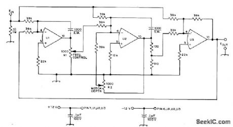
Center frequency of notch can be varied with single control R1; upper limit is about 4 kHz. Circuit Q and notch depth are constant over range. R2 is ad justed initially for best notch depth. All opamps are 741 14-pin DIP,such as Motorola MC1741L. UI and U2 are in-tegrators with DC gain of about 2500, and U3 is summing device. Notch depth is at least 50 dB.may be connected directly across output, or buffer stage can be added to drive lower-impedance loudspeaker or headset. Use with AGC off.-A. Taflove, An Analog-Computer-Type Active Filter, QST, May 1975, p 26-27. (View)
View full Circuit Diagram | Comments | Reading(596)
| Pages:283/471 At 20281282283284285286287288289290291292293294295296297298299300Under 20 |
Circuit Categories
power supply circuit
Amplifier Circuit
Basic Circuit
LED and Light Circuit
Sensor Circuit
Signal Processing
Electrical Equipment Circuit
Control Circuit
Remote Control Circuit
A/D-D/A Converter Circuit
Audio Circuit
Measuring and Test Circuit
Communication Circuit
Computer-Related Circuit
555 Circuit
Automotive Circuit
Repairing Circuit