Filter Circuit
LOW_COST_UNIVERSAL_ACTIVE_FILTER
Published:2009/7/2 2:18:00 Author:May | From:SeekIC
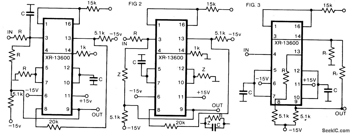
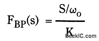
The circuit as shown in Fig. 1 gives the bandpass operation the transfer function calculated from
Interchanging the capacitor C with the resistor R at the input of the circuit high-pass operation is obtained. A low-pass filter is obtained by applying two parallel connections of R and C as shown in Fig. 2.
The low-pass operation may be much improvedwith the circuit as gtven h Fig.3.Here the gamand Q may be set up separately with respectto the cut-off frequency according to theequations
Reprinted Url Of This Article:
http://www.seekic.com/circuit_diagram/Basic_Circuit/Filter_Circuit/LOW_COST_UNIVERSAL_ACTIVE_FILTER.html
Print this Page | Comments | Reading(3)

Article Categories
power supply circuit
Amplifier Circuit
Basic Circuit
LED and Light Circuit
Sensor Circuit
Signal Processing
Electrical Equipment Circuit
Control Circuit
Remote Control Circuit
A/D-D/A Converter Circuit
Audio Circuit
Measuring and Test Circuit
Communication Circuit
Computer-Related Circuit
555 Circuit
Automotive Circuit
Repairing Circuit
Code: