Basic Circuit
5_MHz_FRONT_END
Published:2009/7/6 1:45:00 Author:May | From:SeekIC

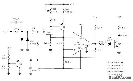
Used ahead of 5-MHz frequency counter to make input signal swing from logic 0 of 0 V to logic 1 of about 10 V as required for accurate counting of frequency for input signal having any input waveform shape and level. Input of front end has high impedance to minimize effect on input waveform. FET transistor Q1 and bipolar buffer Q2 drive Schmitt trigger using half of Motorola MC75:08 dual line receiver.-D. Aldridge, Battery-Powered 5-MHz Frequency Counter, Motorola, Phoenix, AZ, 1974, AN-717, p 5.
Reprinted Url Of This Article:
http://www.seekic.com/circuit_diagram/Basic_Circuit/5_MHz_FRONT_END.html
Print this Page | Comments | Reading(3)

Article Categories
power supply circuit
Amplifier Circuit
Basic Circuit
LED and Light Circuit
Sensor Circuit
Signal Processing
Electrical Equipment Circuit
Control Circuit
Remote Control Circuit
A/D-D/A Converter Circuit
Audio Circuit
Measuring and Test Circuit
Communication Circuit
Computer-Related Circuit
555 Circuit
Automotive Circuit
Repairing Circuit
Code: