Basic Circuit
VHF_antenna_booster
Published:2009/7/23 21:56:00 Author:Jessie | From:SeekIC

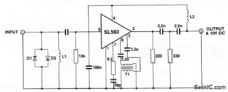
This circuit shows an SL560 amplifier connected as a wideband (40 to 260 MHz) antenna amplifier or booster suitable for any 50-Ω system. D1 and D2 are any general-purpose silicon diodes. L1 is 8 turns of #26, 1/8 intemal diameter.L2 is 20 turns of #26, 3/16 intemal diameter. T1 consists of two lengths of #34 wire approximately 6 long, twisted together (8 twists/inch) and wound on a 6-hole ferrite bead (Mullard FX1898). The circuit is powered through the coaxial cable (+10 V at the coax center, and ground at the coax outer shield), and requires about 30 mA.
Reprinted Url Of This Article:
http://www.seekic.com/circuit_diagram/Basic_Circuit/VHF_antenna_booster.html
Print this Page | Comments | Reading(3)

Article Categories
power supply circuit
Amplifier Circuit
Basic Circuit
LED and Light Circuit
Sensor Circuit
Signal Processing
Electrical Equipment Circuit
Control Circuit
Remote Control Circuit
A/D-D/A Converter Circuit
Audio Circuit
Measuring and Test Circuit
Communication Circuit
Computer-Related Circuit
555 Circuit
Automotive Circuit
Repairing Circuit
Code: