
Circuit Diagram
Index 799
FAN_SPEED_CONTROL
Published:2009/7/17 4:14:00 Author:Jessie

Several 24-V 1.5-A transformers can be used as a speed control, where a triac would be usable,such as on an induction motor. Connect the primaries in parallel and shown. (View)
View full Circuit Diagram | Comments | Reading(672)
Norton_amplifier_with_high_input_impedance_and_high_gain
Published:2009/7/17 4:14:00 Author:Jessie
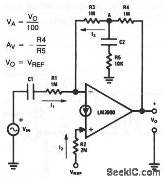
This circuit uses one section of an LM3900 to form an ac amplifier with both high input impedance (1 MΩ) and high gain (100). National Semiconductor, Linear Applications Handbook 1991 p 221. (View)
View full Circuit Diagram | Comments | Reading(710)
ELLIPTICAL_PAITERN
Published:2009/7/10 22:21:00 Author:May

Connection shown gives Lissajous-type elliptical pattern on CRO from ordinary AF signal generator. Modulation can be added to eithervertical or horizontal feed for CRO.-Novice Q & A, 73 Magazine, March 1977, p 187. (View)
View full Circuit Diagram | Comments | Reading(639)
B_H_LOOP_DISPLAY
Published:2009/7/10 22:21:00 Author:May

Low-cost dual opamp circuit allows display of hysteresis loop on call-brated XY oscilloscope. Two windings are placed on core to be tested, with opamp of fluxmeasuring system connected to secondary for deriving vertical deflection input representing flux B. Artide gives design equations and details of circuit operation and use.-D. A. Zinder, X-Y Oscilloscope Displays Hysteresis Loop of Any Core, EDN Magazine, Feb. 5, 1975, p 54-55. (View)
View full Circuit Diagram | Comments | Reading(1474)
MICROPOWER_THERMOMETER
Published:2009/7/10 22:20:00 Author:May


Low power consumption makes circuit attractive for battery-operated equipment. Uses National LX5600 temperature transducer covering -55℃ to +125℃, whose output is directly propor-tionalto absolutetemperature at l0 mV/K, Both zero and scale factor ale independently selectable. Thermometer is pulsed at low duty cycle to reduce power consumption, with sample and hold usedto obtain continuous output between pulses. Supply range is 8-12 V; 8.4-V mercury battery will give over 1 year of operational Iife. Output can be used to drive meter for direct readout. MVBR Q1-Q2 drives LX5600 through R9. C1 and R3 control OFF time, and C1, R1, R4, and R7 control ON time. Q3 issample transistor. Output is 0-50 μA for 50-100°F temperature change. Formulas in box give values for other ranges.-R. C. Dobkin, Micropower Thermometer, National Semiconductor, Santa Clara, CA, 1974, LB-27. (View)
View full Circuit Diagram | Comments | Reading(1315)
ASCLL_TO_HEX_CONVERTER
Published:2009/7/10 22:19:00 Author:May

Simple two-chip circuit takes ASCLL data from keyboard and converts characters 0-9 and A-F to 4-bit hexadecimal machine-tanguage format, as required for loading operating system initially into 1802-based microprocessor system. Once loaded, further code conversion can be achieved with software.-E. Copes, 0ne Keyboard: Hex and ASCLL, Kilobaud, June 1978, p 57. (View)
View full Circuit Diagram | Comments | Reading(773)
COLOR_FOR_TV_TYPEWRITER
Published:2009/7/10 22:19:00 Author:May

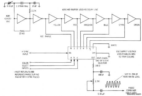
Uses 3.579545-MHz crystal osdllator to drive string of CMOS buffers forming digital delay line. Output delays caused by propagation times in each buffer can be used directly or can be trimmed to specific colors by varying supply voltage. Reference phase and delayed color outputs go to 1-of-8 data selector whose output is determined by code presented digitally to its three color select Iines. Selector drive Iogic must retum to 000 (reference phase) immediately before, during, and for at least several microseconds after each.horizontal sync pulse so set can lock and hold on reference color burst. Sine-wave output chrominance signal is cut down to about one-fourth of maximum video white level.-D. Lancaster, TV Typewriter Cookbook, Howard W Sams, Indianapolis, IN, 1976, p 205-206. (View)
View full Circuit Diagram | Comments | Reading(1830)
TELEPHONE_RINGER
Published:2009/7/10 22:19:00 Author:May
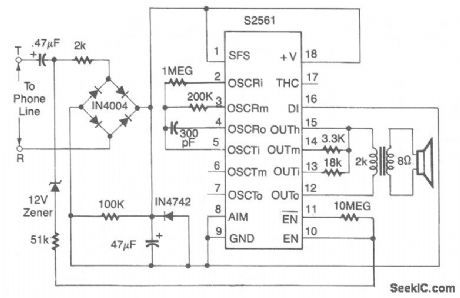
Using an AMI P/N S2561 IC, the circuit shown can be either powered by a battery or the telephone line in use. Output is about 50 mW. (View)
View full Circuit Diagram | Comments | Reading(0)
Fire_siren_using_an_LM3909_chip
Published:2009/7/17 4:47:00 Author:Jessie

Fire siren using an LM3909 chip. Circuitry inside dashed lines is the LM3909.This circuit produces a rapidly rising sound when pressing the pushbutton and a coasting sound upon release (courtesy National Semiconductor Corporation). (View)
View full Circuit Diagram | Comments | Reading(711)
TV_INTERFACE_FOR_TYPEWRITER
Published:2009/7/10 22:18:00 Author:May
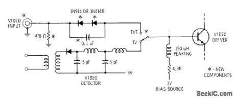
Video input circuitfor black and white transistor TV receiver permits feeding video output of TV typewriter to video driver in set, for producing character or DRIVER game display on TV screen. Use of direct coulpling eliminates shading effect or changes in background level as characters are added.Diodes provide 1.2-V offset in positive direction so in absence of video the video driver is biased to blacker-than-black sync level of 1.2 V. With white video input of 2 V, driver is biased to usual 3.2 V of white level. Hot-chassis TV sets can present shock hazard.-D, Lancaster, TV Typewriter Cookbook, Howard W. Sams, Indianapolis, IN, 1976, p 190. (View)
View full Circuit Diagram | Comments | Reading(1200)
FAIL_SAFE_COMMUNICATIONS_SQUELCH_CIRCUIT
Published:2009/7/17 4:47:00 Author:Jessie

Circuit adjusts automatically to changing noise levels in point-to-point vhf and uhf receivers while suppressing noise when no carrier is present, but stays open when receiver gain is below threshold level of 0.7 microvolt over range of 108.95 to 135.95 Mc. Schmitt trigger gives fast turn-on and turn-off of receiver audio output at predetermined carrier-to-noise ratios.-H. G Michael, Fail-Safe Squelch Circuit Adapts to Changing Noise levels, Electronics, 36:1, p 88-91. (View)
View full Circuit Diagram | Comments | Reading(755)
Norton_precision_comparator
Published:2009/7/17 4:46:00 Author:Jessie
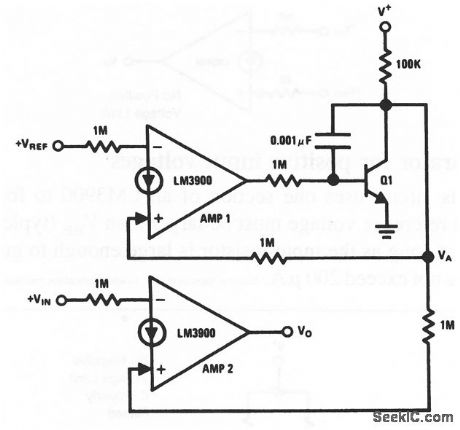
This circuit uses two sections of an LM3900 to form a precision comparator. The current established by VREF at the (-) input of amplifier 1 causes Q1 to adjust VA. The value of VA causes an equal current to flow into the (+) input of amplifier 2. This current corresponds more exactly to the reference current of amplifier 1 National Semiconductor, Linear Applications Handbook 1991 p 244. (View)
View full Circuit Diagram | Comments | Reading(754)
Whooper_siren_using_two_LM3909_chips
Published:2009/7/17 4:46:00 Author:Jessie

Whooper siren using two LM3909 chips (courtesy National Semiconductor Corporation). (View)
View full Circuit Diagram | Comments | Reading(736)
OPTOISOLATOR_FOR_PROBE
Published:2009/7/10 22:18:00 Author:May

Offsets need for potentially dangerous practice of floating oscilloscope with respect to ground. Also permits simultaneous display of two voltages with correct polarity on double-beam oscilloscope when one of them is floating. Texas Instruments TIL112 optocoupler used has bandwidth of about30 kHz, Three rangesgive choice of 1 :1, 10:1, and 100:1 input attenuation. Set RV2 to bias phototransistor of optocoupler to center of its linear range (about 4.5 V between pins 4 and 5), then set RV1 to give unity input/output ratio on range 1. RV3 is set to give zero DC output when input telminals are shorted, but can be omitted if zeroing of output level is unnecessary.-A. F. Sargent, Simple C.R.O. Input Isolating Probe, Wireless World, Feb. 1976, p 76. (View)
View full Circuit Diagram | Comments | Reading(1178)
Electronic_trombone_using_an_LM3909_chip
Published:2009/7/17 4:46:00 Author:Jessie

Electronic trombone using an LM3909 chip. Circuitry inside dashed lines is the LM3909. The location and surroundings of the speaker determine the frequency output. Construct a cubical box roughly 64 cubic inches with one end that is able to slide in and out like a piston. The box should be stiffened with thin layers of pressed wood. Minimum volume should be 10 cubic inches. Speaker, circuit and battery should be mounted in the sliding end. A tube 21/2 inches long with an inside diameter of 5/16 inch should be provided to bleed air in and out as the piston moves (courtesy National Semiconductor Corporation). (View)
View full Circuit Diagram | Comments | Reading(751)
AIR_VELOCITY_METER
Published:2009/7/10 22:17:00 Author:May

Uses National LX5600 air temperature reference, connected in unitygain mode, in combination with LX5700 selfheated velocity sensor to convert wind velocity or airspeed to differential between heated and unheated transducers. As wind velocity rises, heating current required to hold velocity sensor predetermined number of degrees above ambientis measured. Calibration curve is drawn to show correlation between current and airspeed.-P. Lefferts, A New Interfacing Concept; the Monolithic Temperature Transducer, National Semiconductor, Santa Clara, CA, 1975, AN-132, p 8. (View)
View full Circuit Diagram | Comments | Reading(1647)
EYEBALL_PRESSURE_GAGE
Published:2009/7/17 4:45:00 Author:Jessie
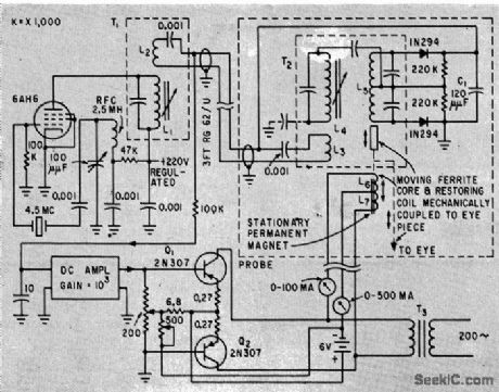
Moving ferrite core in probe deflects in proportion to eyeball pressure and produces signal that is amplified to drive recorder. Plateau of re corded response represents true pressure, which can easily be read independently of peak caused by extra pressure of probe.-R. S. Mackay and E. Marg, Electronic Tono-meter for Glaucoma Diagnosis, Electronics, 33:7, p 115-116. (View)
View full Circuit Diagram | Comments | Reading(709)
5O0_W_VARIAB[E_PULSE_WIDTH_REGULATOR
Published:2009/7/10 22:16:00 Author:May

Chopper transistor supplies pulsewidth-modulated pulses to averaging circuit and filter. Filter output voltctge is compared to extemal reference voltage by magnetic am plifier, which changes pulse width to decrease devicttion. Chopper is driven by two-transistor square-wave oscillator modulated by mag-netic amplifier.-P. Bahhasctr, New Iransistor Regukttor Handles 500-Watt Outputs, Elec-tronics, 35:38, p48-49. (View)
View full Circuit Diagram | Comments | Reading(516)
NEGATIVE_INPUT_CURRENT_REGULATOR
Published:2009/7/17 4:45:00 Author:Jessie

Opamp is used as inverter starting current-boosting transistor to provide positive supply voltage. Load current range depends on transistor used.R3 forcesQ1 to conduct much heavier current than feedback current, as required for high load current. Current gain depends on ratio of R2 to R3-W. G. Jung, IC Op-Amp Cookbook, Howard W. Sams, Indianapolis, IN, 1974, p 176-177. (View)
View full Circuit Diagram | Comments | Reading(698)
HEXADECIMAL_ENTRY
Published:2009/7/10 22:15:00 Author:May

Permits entering program into microprocessor in hexadecimal notation, in much less time than is required with binary notation. Binary switches from input port of μP are replaced with 16-key keyboard shown. To enter hexadecimal number 3B, turn on power; press 3 button, press decimal bar, then press B button; operate loading switch, then press decimal bar again to set keyboard for next entry. Article traces keyboard operation through circuit.-B. K. Erickson, Talk to Your μP with a Hex-Latching Keyboard, EDN Magazine, Nov. 20, 1976, p 319-320. (View)
View full Circuit Diagram | Comments | Reading(2011)
| Pages:799/2234 At 20781782783784785786787788789790791792793794795796797798799800Under 20 |
Circuit Categories
power supply circuit
Amplifier Circuit
Basic Circuit
LED and Light Circuit
Sensor Circuit
Signal Processing
Electrical Equipment Circuit
Control Circuit
Remote Control Circuit
A/D-D/A Converter Circuit
Audio Circuit
Measuring and Test Circuit
Communication Circuit
Computer-Related Circuit
555 Circuit
Automotive Circuit
Repairing Circuit