
Circuit Diagram
Index 792
TEMPERATURE_CONTROLLER_WITH_DEFROST_CYCLE
Published:2009/7/11 0:10:00 Author:May

This temperature controller has a range of -50 to +150°C and permits defrosting. R7, VR3, and R8 set the controller's trip point. 51 initiates defrosting, S2 cancels defrosting. VR1 and VR2 set the defrost-temperature trip point.The LM134, IC1, is a thermal sensor. One section of IC3, a quad op amp, buffers the sensor's output. The other section func-tions as Schmitt trigger and buffer for the normal-cycle circuitry and as a comparator for the defrost-cycle circuitry. If you wish to control a heater rather than a refrigerator, omit the final inverter in Q1's base circuit. You must select LM7805s that have outputs between 4.95 and 5.05 V, or the circuit might not work. (View)
View full Circuit Diagram | Comments | Reading(1559)
Logarithmic_current_source
Published:2009/7/17 3:57:00 Author:Jessie

This circuit uses both sections of an XR-13600 (Fig. 11-1B) to form a logarithmic current source. The current can be used for IB (the bias current) in many OTA applications by providing a logarithmic current output for a linear voltage in.For example, the circuit can be used to bias the stereo volume control (Fig. 11-2) to provide temperature-independent stereo attenuation characteristics. EXAP Corporation Databook 1990 p5- 258 (View)
View full Circuit Diagram | Comments | Reading(1016)
lOO_KG_CLOCK_FOR_COUNTER
Published:2009/7/10 23:56:00 Author:May


Stable fixed-frequency Pierce oscillator becomes transistorized Clapp oscillator when crystcd is replaced by high-Q L-C tuner.-W Fryer,How to Design Low Cost Audio Filters,Elecltonics,32:15,p68-70. (View)
View full Circuit Diagram | Comments | Reading(584)
_5_V_AT_4A_12_V_AT_025_AAND__24_V_AT_2_A
Published:2009/7/17 3:57:00 Author:Jessie

Provides regulated voltages needed for Sykes 7158 floppy disk and its interface controller, used in Southwest Technical Products MP-68 computer system. Circuit provides adjustable current limiting and overvoltage protection on 5-V supply. Output voltage adjustments are provided for 5-V and 24-V supplies. - P. Hughes, Interfacing the Sykes OEM Floppy Disk Kit to a Personal Computer, BYTE, March 1978, p 178-185. (View)
View full Circuit Diagram | Comments | Reading(1536)
DRIVER_FOR_24_MOS_REGISTERS
Published:2009/7/10 23:56:00 Author:May

With input of clock pulses preshaped to width of about 150ns, circuit shown will generate 17-V,1.5-A clocksignal required for driving 1024-bit serial MOS memories or shift registers Article traces operation of circuit All diodes are 1N3064.-R. D. Hoose and G. L. Anderson, Clock Driver for MOS Shift Registers,EDN|EEE Magazine.Dec, 15, 1971, p 56-57. (View)
View full Circuit Diagram | Comments | Reading(594)
Pulse_width_modulator
Published:2009/7/17 3:56:00 Author:Jessie

This circuit uses both sections of an XR-13600 (Fig. 11-1B) to form a pulse-width modulator. EXAR corporation Databook 1990 p 5-258 (View)
View full Circuit Diagram | Comments | Reading(0)
60_Hz_GLITCH_FREE_CLOCK
Published:2009/7/10 23:54:00 Author:May

Circuit generates complementary gated 60-Hz dock pulses that are always wider than 2 μs, without glitches even if gate is enabled or disabled during clock pulse. Accuracy depends on stability of powerline frequency.-R. I. White, Gated 60 Hz Clock Avoids Glitches, EDN|EEE Magazine, Nov. 1, 1971,p 52. (View)
View full Circuit Diagram | Comments | Reading(607)
SEALED_COIL_TESTER
Published:2009/7/10 23:54:00 Author:May

Permits rapid nondestructive testing of hermetically sealed coils for shorted or open turns, coil-to-core shorts, and reversed polarity of connections. Can be used for simultaneous testing of all coils in recording heads for up to 18 tracks. Circuit develops test pulse having predetermined polarity, amplitude, and duration. Article gives details of circuit operation and test procedures. With multiple-coil units, lamp and detector circuit must be provided for each coiL-D. L. Uhls, Novel Method Nondestructively Tests Sealed Coils, EDNMagazine, March 20, 1976, p 102 and 104. (View)
View full Circuit Diagram | Comments | Reading(1252)
TGS_gas_smoke_detector_with_triac_control
Published:2009/7/17 3:56:00 Author:Jessie

TGS gas/smoke detector with triac control(courtesy Motorola Semiconductor Products Inc.). (View)
View full Circuit Diagram | Comments | Reading(746)
800_Hz_CLOCK_FOR_CASSETTE_RECORDER
Published:2009/7/10 23:54:00 Author:May

565 PLLis set for free-running at 800 Hz with no input. When data pulses extracted from FSK recorded data on cassette tape are fed in,clock is synchronized to data and stays in sync for up to seven 0s in succession.- Signetics AnalogData Manual, Signetics,Sunnyvale,CA,1977,p 859-860. (View)
View full Circuit Diagram | Comments | Reading(1228)
MOISTURE_DETECTOR
Published:2009/7/17 3:56:00 Author:Jessie

This simple circuit can save your house from water inundation. Also, it can save your electrical equipment from water damage. When raindrops fall on the water sensor, a small current flows, turning on Q1 and the buzzer. Alternatively, you could replace the buzzer with a relay to drive a pump. The water sensor can be made from an etched circuit board. (View)
View full Circuit Diagram | Comments | Reading(6431)
25_NSEC_O5_AMP_CLOCK_PULSE_GENERATOR
Published:2009/7/10 23:53:00 Author:May
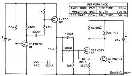


Used in computer circuits to set timing for array of circuits.Mvbr Q1-Q2 triggers pulse generator Q3-Q4.- Transistoy Manual, Seventh Edition, General Electric Co, 1964, p202. (View)
View full Circuit Diagram | Comments | Reading(543)
CRYSTAL_CHECKER
Published:2009/7/10 23:53:00 Author:May

Simple oscillator circuit checks crystal activity and resonant frequency, as required when choosing matched crystals for filters, For frequency check, signal from oscillator is injected into frequency counter. Values shown are for crystals around 5.5 MHz. For matching purposes, higheraccu racy is obtained by reading harmonics of oscillator.-J. Perolo, Practical Considerations in Crystal-Filter Design, Ham Radio, Nov. 1976, p 34-38. (View)
View full Circuit Diagram | Comments | Reading(3127)
WATER_DETECTOR
Published:2009/7/17 3:54:00 Author:Jessie

The heart of the circuit is the LM1830 fluid detector. It contains all the circuitry needed to sense fluid levels and activate an external device (relay, etc). The IC generates an ac signal that is passed through two probes in the fluid. The IC's detector circuit senses the presence or absence of fluid by comparing the resistance between the probes with its internal reference resistance. When the probes detect the presence of water, the LM1830 will trigger Q1, and that in turn will trigger IC2 (an LM555), which starts a timing period. The output from pin 3 of IC2 closes the relay, and the bilge pump is activated for the duration of the timing period. The timing period is adjustable using R6, a 1-MΩ potentiometer. For the values shown, and depending on the setting of R6, the timing period is about 5 to 120 s. Components R4, D1, and C7 are tied to pin 4 of IC2 to hold the timer at RESET when power is first applied. (View)
View full Circuit Diagram | Comments | Reading(2857)
DIODE_CURVE_TRACER
Published:2009/7/10 23:51:00 Author:May

Circuit is designed to produce voltage-current characteristic curve of diode or other two-terminal device on oscilloscope. Sweep input can be any low-voltage AC source, such as 20-V Variac. Three-terminal devices may be traced if suitable external bias is provided. Opamps are 741.-S. Cahill, Diode Curve Tracer for Oscilloscope, Wireless World, Feb. 1976, p 76. (View)
View full Circuit Diagram | Comments | Reading(1074)
CHECKING_DIODES_WITH_CRO
Published:2009/7/10 23:50:00 Author:May

Simple oscilloscope setup checks and matches diodes. Sort diodes according to type, set potto givedesired trace size for good diode, then note relative sizes of traces obtained for unknown diodes. Reject diodes showing fuzz or ripple on oscilloscope trace.-Novice Q & A, 73 Magazine, March 1977, p 187. (View)
View full Circuit Diagram | Comments | Reading(533)
Log_amplifier
Published:2009/7/17 3:54:00 Author:Jessie

This circuit uses both sections of an XR-13600 (Fig. 11-1B) to form a log amplifier. The amplifier responds to the ratio of current through Q3/Q4. Zero temperature dependence for VOUT is ensured because the TC of the A2 transfer function is equal and opposite to the TC of the transistors. EXAR Corporation Databook 1990 p 5-258 (View)
View full Circuit Diagram | Comments | Reading(2050)
High_performance_high_noise_rejection_two_wire_data_transmission_system
Published:2009/7/17 3:54:00 Author:Jessie

High-performance high-noise-rejection two-wire data transmission system. Instrumentation amplifier 610 amplifies the low-level transducer signal to apply to the 458 V/F converter. A differential line driver is used to drive the twisted pair. A differential line receiver is used to drive the 453 F/V converter, which in turn powers the analog meter (courtesy Analog Devices, Inc.). (View)
View full Circuit Diagram | Comments | Reading(547)
Voltage_reference_with_variable_TC
Published:2009/7/17 3:53:00 Author:Jessie

This circuit uses both sections of an XR-13600 (Fig. 11-1B) to form a voltage reference with variable temperature coefficient. The 100-kΩ potentiometer adjusts the output voltage, which has: 1) a positive TC above 1.2 V, 2) zero TC at about 1.2 V, and 3) a negative TC below 1.2V. This is done by balancing the TC of the A2 transfer function against the complementary TC of D1. EXRA Corporation Databook 1990,p 5-257 (View)
View full Circuit Diagram | Comments | Reading(622)
High_noise_immunity_data_transmission_system_using_a_V_F_converter
Published:2009/7/17 3:52:00 Author:Jessie

High-noise immunity data transmission system using a V/F converter. Model 610, an instrumentation amplifier, amplifies the low-level differential transducer signal up to the 10-voltfull scale input level of the452V/F convener. A differential line driver is used to drive a twisted pair. A differential line receiver is used to drive the digital counter and display (courtesy Analog Devices, Inc.). (View)
View full Circuit Diagram | Comments | Reading(529)
| Pages:792/2234 At 20781782783784785786787788789790791792793794795796797798799800Under 20 |
Circuit Categories
power supply circuit
Amplifier Circuit
Basic Circuit
LED and Light Circuit
Sensor Circuit
Signal Processing
Electrical Equipment Circuit
Control Circuit
Remote Control Circuit
A/D-D/A Converter Circuit
Audio Circuit
Measuring and Test Circuit
Communication Circuit
Computer-Related Circuit
555 Circuit
Automotive Circuit
Repairing Circuit