
Circuit Diagram
Index 788
25_kHz_CLOCK
Published:2009/7/11 1:32:00 Author:May

Requires only 3-mW power to generate fast 15-V two-phase rectangular pulses with 100-ns widths and 20-ns rise and fall times. Suitable for many MOSFET shift regiters. Uses two D13T1 programmable UJT oscillators, each having four-transistor driver stage using 2N2369 transistors. Oscillators are crosssynchronized by 130-pF capacitor. Timing and bias networks of UJTs set pulse repetition frequency.-G. A. Altemose, Low-Power Two-Phase Clock, EDN|EEE Magazine, May 15, 1971, p 49. (View)
View full Circuit Diagram | Comments | Reading(785)
TWO_DIMENSIONAL_TARGET_SIMULATOR
Published:2009/7/17 3:05:00 Author:Jessie

Two signals, one representing angular position of target and the other angular position of radar antenna, are fed to azimuth coincidence circuit. When signals coincide, indicating that antenna is pointing at target, delayed pulses representing a target are passed to radar ppi by azimuth gating circuit.-J. I. Leskinen, Four Ways to Simulate Radar Targets, Electronics, 31:23, p 82-86. (View)
View full Circuit Diagram | Comments | Reading(831)
LOW_POWER_HF_TRANSMITTER
Published:2009/7/11 1:28:00 Author:May

This transmitter runs up to 1/2W on the 40-m amateur band. Coils are wound on T25 and FT23 toroids, respectively. Point A is connected to point B to key the oscillator, along with the ftnal (point C) to leave the oscillator running constantly. Use 1/10-W resistors and VERY small components. (View)
View full Circuit Diagram | Comments | Reading(1597)
EDDY_CURRENT_CLADDING_THICKNESS_GAGE
Published:2009/7/17 3:04:00 Author:Jessie

Low-frequency channel (47.5 kc) obtains thickness of cladding on reactor fuel elements. Probe is common element of each input bridge. Can also be used for measuring plating thickness or for detection of sub-surface cracks and voids.-W. J. McGonnagle, C. J. Renken, and R. G. Myers, Improved Nondestructive Testing by Eddy-Currents, Electronics, 32:35, p 42-43. (View)
View full Circuit Diagram | Comments | Reading(633)
20_m_CW_TRANSCEIVER
Published:2009/7/11 1:26:00 Author:May


The Colpitts VFO circuit (Fig. 93-1(a)) has gate clamping to improve stability. It is followed by two buffers: the second provides individual outputs to the transmitter and receiver. An RIT circuit operates on receive. The front end uses 40673 dual-gate MOSFETs (Fig. 93-1(b)). The tuned circuits are peaked to the center of the CW band with the trimmer. The mixer output is link-coupled to a KVG 9-MHz SSB filter whose output is amplified by an SL612 IF amplifier IC (Fig. 93-1(c)).The product detector uses two BC107 transistors. Carrier reinjection is from a crystal oscillator using the USB crystal supplied with the KVG filter. Figure 93-1(d) and 93-1(e) contain: an FET oscillator and a pnp bipolar oscillator. Use either or alter the circuit polarities to suit an npn transistor. The transmitter mixer is an MD108 (Fig. 93-1(f)), fed from the VFO and the LSB carrier-injection oscillator.A simple diode/meter circuit measures the relative power output (Fig. 93-1(g)). Sidetone is provided by an NE555 circuit (Fig. 93-1(h)). (View)
View full Circuit Diagram | Comments | Reading(2016)
Long_term_precision_integrator_for_such_things_as_pollution_monitoring
Published:2009/7/17 3:04:00 Author:Jessie

Long-term precision integrator for such things as pollution monitoring. The analog signal is applied to precision input amplifier model 52K, then to the V/F convener input. Model 458 is a 100 kHz V/F converter while model 460 is a 1 MHz V/F convener. The V/F output is connected to a large capacity counter and display, operating as a totalizer. The total pulse count is equal to the time integral of the analog input signal (courtesy Analog Devices, Inc.). (View)
View full Circuit Diagram | Comments | Reading(676)
DELAY_LINE_AMPLIFIER_FOR_CLUTTER_SIMULATOR
Published:2009/7/17 3:03:00 Author:Jessie
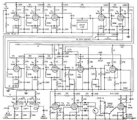
Used with ultrasonic delay line and 30-Mc Gaussian noise source to simulate actual clutter received during consecutive radar sweeps. Input 1 is amplified version of delay line output signal, which is added to noise input 2 in common plate load of V1 and V2, for amplification by V3. These three tubes together with tuned input to delay line form staggered Butterworth triple centered on 30 Mc, with half-power band-width of 2.75 Mc. Third input permits insertion of pulse for precise synchronizing lo repetition frequency of clutter simulator.-J. Atkin, H. J. Bikel, and M. Weiss, Realistic Simulation of Radar Clutter, Electronics, 32:39, p 78-81. (View)
View full Circuit Diagram | Comments | Reading(713)
TIME_ON_TOUCH_SWITCH
Published:2009/7/11 1:23:00 Author:May

The circuit is built around a 555 oscillator (U1), which is tumed on when a trigger is applied by touching the touch terminal to pin 2 of U1. When activated, LED1 and BZ1 (a piezoelectric buzzer) tum on for the time period set by the values of R2 and C1. The ON-time of the touch circuit can be altered by changing the values of Q and R2.This touch switch can be powered from batter-ies so that it need not be near a 60-Hz power source for triggering. The extremely small amount of current supplied to the trigger input through the 10-MΩ resistor. R1, makes the input circuitry very sensitive to any external loading, and it is easily triggered by touching the pickup. (View)
View full Circuit Diagram | Comments | Reading(783)
WWV_RECEIVER
Published:2009/7/17 3:03:00 Author:Jessie

This receiver is a crystal-controlled superheterodyne receiver with an MPF102 RE amplifier, NE602 mixer, ceramic IF filter, MC1350P IF amplifier, ZN414 AM detector, and MC34119 audio output. The AGC system uses a CA3140E op amp. A 9545-kHz crystal is used in the LO. (View)
View full Circuit Diagram | Comments | Reading(7)
HUM_DETECTING_TOUCH_SENSOR
Published:2009/7/11 1:22:00 Author:May
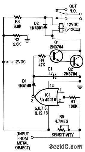
This touch sensor uses the 60-Hz hum pickup by the human body to drive a detector and relay drivers, Q1 and Q2. R5 controls sensitivity of the circuit. (View)
View full Circuit Diagram | Comments | Reading(1214)
Precision_integrator_using_the_Datel_AM_490_2_8_pin_TO_99_
Published:2009/7/17 3:03:00 Author:Jessie

Precision integrator using the Datel AM-490-2 8-pin TO-99 (courtesy Datel Systems, Inc.). (View)
View full Circuit Diagram | Comments | Reading(508)
TOUCH_SWITCH_Ⅱ
Published:2009/7/11 1:21:00 Author:May

U1A and U1B/U1C/U1D form a bistable multivibrator that drives Q1, which switches the load. Touching the two upper contacts makes Q1 conduct; the two lower contacts cause Q1 to cut off. (View)
View full Circuit Diagram | Comments | Reading(630)
AUDIO_INTERPOLATING_PHASE_SHIFTER
Published:2009/7/17 3:03:00 Author:Jessie

A simple interpolating phase shifter places a negative resistance across potentiometer X to obtain constant-amplitude, linear-phase performance. (View)
View full Circuit Diagram | Comments | Reading(644)
CABLE_DRIVE_FOR_VELOCIMETER
Published:2009/7/17 3:02:00 Author:Jessie

Flip-flop frequency divider converts 7-kc pulse output of velocimeter to 3.5 kc while providing low impedance and sufficient driving power for sending pulses through up to 35,000 feel of cable to counter on surface vessel.-L. Dulberger, Deep-Ocean Velocimeter Aids Sonar Systems Design, Electronics, 34:22, p 41-43. (View)
View full Circuit Diagram | Comments | Reading(850)
High_speed_integrator_using_an_ECG915_operational_amplifier
Published:2009/7/17 3:02:00 Author:Jessie
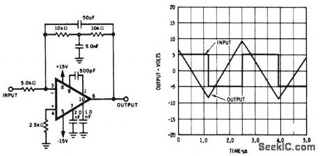
High-speed integrator using an ECG915 operational amplifier (courtesy GTE Sylvania Incorporated). (View)
View full Circuit Diagram | Comments | Reading(673)
ON_OFF_TOUCH_SWITCH
Published:2009/7/11 1:20:00 Author:May

This circuit uses a CA3240 dual BiMOS op amp to sense small currents flowing between the contact points on a touch plate. The high input impedance of the CA3240 allows the use of 1-MΩ resistors in series with the touch plates to ensure user safety. A positive output on either pin 7 (ON) or pin 1 (OFF) of the CA3240 actuates the CA3059 zero-voltage switch, which then latches the triac on or turns it off. The internal power supply of the CA3059 powers the CA3240. (View)
View full Circuit Diagram | Comments | Reading(0)
TOUCH_SWITCH_Ⅰ
Published:2009/7/11 1:18:00 Author:May

This switch reacts to the touch of a finger to turn lights and/or appliances on or off. The device uses the human body as an antenna to pick up 60-Hz hum, which is applied to a metal plate by your finger. The signal is fed to the input of U1, an LM380 audio-power amplifier. An LM386 should work as well.The 60-Hz output from the amplifier is rectified by D1 and D2, then filtered by C3. Potentiometer R3 sets the trigger voltage used to saturate Q1. When Q1 turns on, the collector end of R4 goes almost to ground and provides the needed voltage to turn on Q2. Transistor Q2 turns on and clocks. The flip-flop is configured for toggle-mode operation, so its output switches states with each clock pulse.The 4027 (U2) is wired to toggle by tying the J and K inputs high and the set and resets low. Transis-tor Q3 is connected to the Ooutput through the 4.7-kΩ resistor. Transistor Q3 drives Q4, the relay driver. Be sure that the load does not exceed the relay ratings. (View)
View full Circuit Diagram | Comments | Reading(919)
5_MC_CRYSIAL_FREQUENCY_CONTROL
Published:2009/7/11 1:16:00 Author:May

C1 provides fine frequency control of 5-Mc primary frequency standard, when driven by 100-cps control signctl from cesium beam tube.This will change frequency up to 2.5 cps,sufficient for short-lime drifts over several days. When C1 reaches either end of its range, cam doses s1 or s2 and energizes drive motor M1 for C2. Lorge capacitor is then driven in direction that will make small capacitor return to middle of its range.-W.A. Mainberger, Primary Frequency Standard Using Resonant Cesium, Electronics, 31:45, p80-85. (View)
View full Circuit Diagram | Comments | Reading(530)
SENSOR_SWITCH_AND_CLOCK
Published:2009/7/11 1:16:00 Author:May

One TL084 IC and an old quartz watch enable the construction of a deluxe on/off switch. Two of the four op amps contained in the TL084 (A1 and A2) are used to amplify the input signals from the sensors by one hundredfold (with the component values as shown in the diagram). Just touching the sensors with a finger causes a good 50-Hz input signal (hum). Notice that the amplification drops rapidly with rising fre-quency.Diodes D5 and D6 rectify (single-phase) the 50-Hz signal. Because the diodes are connected in anti-phase, touching the off sensor causes a positive potential across C10, whereas touching the on sen-sor produces a negative potential across C10.Op amp A4 is connected as an inverting bistable so that a negative potential across C10 causes relay Re1 to be energized. Because of feedback resistor R16, this state is maintained until the other sensor is touched.The relay can also be energized at a predetermined time with the aid of a quartz watch. The 1.2-V supply for the watch is derived from the voltage drop across diodes D9 and D10; it can be increased to 1.8 V by adding a third diode.The piezo buzzer in the watch is connected to the input of A3 via C5. As soon as the alarm goes off (the hour signal must be off), the voltage across C10 becomes negative, the relay is energized, and the load is switched on. The circuit, excluding the relay, draws a current of about 20 mA. (View)
View full Circuit Diagram | Comments | Reading(4813)
TREMOLO_CIRCUIT
Published:2009/7/11 1:14:00 Author:May

This circuit adds a VLF AM component to an audio signal. This effect is widely used in musical instru-ments. U1C, a phase-shift oscillator operating at a few Hz applies a signal to Q1, which modulates the gain of U1D. R11 varies the level of the effect, while R12 varies the frequency. (View)
View full Circuit Diagram | Comments | Reading(820)
| Pages:788/2234 At 20781782783784785786787788789790791792793794795796797798799800Under 20 |
Circuit Categories
power supply circuit
Amplifier Circuit
Basic Circuit
LED and Light Circuit
Sensor Circuit
Signal Processing
Electrical Equipment Circuit
Control Circuit
Remote Control Circuit
A/D-D/A Converter Circuit
Audio Circuit
Measuring and Test Circuit
Communication Circuit
Computer-Related Circuit
555 Circuit
Automotive Circuit
Repairing Circuit