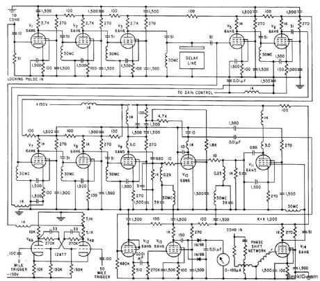
Amplifier Circuit
DELAY_LINE_AMPLIFIER_FOR_CLUTTER_SIMULATOR
Published:2009/7/17 3:03:00 Author:Jessie | From:SeekIC

Used with ultrasonic delay line and 30-Mc Gaussian noise source to simulate actual clutter received during consecutive radar sweeps. Input 1 is amplified version of delay line output signal, which is added to noise input 2 in common plate load of V1 and V2, for amplification by V3. These three tubes together with tuned input to delay line form staggered Butterworth triple centered on 30 Mc, with half-power band-width of 2.75 Mc. Third input permits insertion of pulse for precise synchronizing lo repetition frequency of clutter simulator.-J. Atkin, H. J. Bikel, and M. Weiss, Realistic Simulation of Radar Clutter, Electronics, 32:39, p 78-81.
Reprinted Url Of This Article:
http://www.seekic.com/circuit_diagram/Amplifier_Circuit/DELAY_LINE_AMPLIFIER_FOR_CLUTTER_SIMULATOR.html
Print this Page | Comments | Reading(3)

Article Categories
power supply circuit
Amplifier Circuit
Basic Circuit
LED and Light Circuit
Sensor Circuit
Signal Processing
Electrical Equipment Circuit
Control Circuit
Remote Control Circuit
A/D-D/A Converter Circuit
Audio Circuit
Measuring and Test Circuit
Communication Circuit
Computer-Related Circuit
555 Circuit
Automotive Circuit
Repairing Circuit
Code: