
Circuit Diagram
Index 783
KEYEB_WITH_4VlEMORY
Published:2009/7/11 2:17:00 Author:May

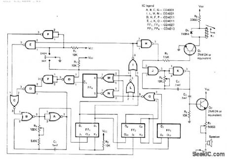
Includes sidetone oscillator and dash-dot memory along with variable speed, automatic spacing, and self-completing dots and dashes. If dot paddleis pressed and released while keyer is generating dash, dot is generated with correct spacing after dash is completed. Gates A, B, and C form gated MVBR.Gates D, E, O, and P serve to complete characters. JK flip-flops FF1 and FF2, D flip-flop FF3, and gates F, G, and L provide character-shaping required for dash-dot memory using gates M, N, and RS flip-flop FF4. Gates J and K generate audio sidetone. K1 is B & F Enterprises ERA21061 SPST reed relay. Supply can be 9-V battery.-T. R. Crawford, A Low-Power Cosmos Electronic Keyer in Two Versions, CQ, Nov.1975, p 17-24. (View)
View full Circuit Diagram | Comments | Reading(751)
CQ_ON_TAPE
Published:2009/7/11 2:12:00 Author:May
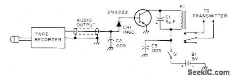
Frequently used code message such as amateur radio CQ call is recorded by keying audio oscillator with desired message and picking up oscillator output with microphone of endless-loop cassette or other tape recorder. Rewound recording is played back through single-transistor stage connected as shown for driving keying relay of transmitter.Circuit requires shielding.-Circuits, 73 Magazine, July 1977, p 34. (View)
View full Circuit Diagram | Comments | Reading(729)
MORSE_CODE_SET
Published:2009/7/11 2:12:00 Author:May

National LM3909 flasher IC is connected as tone oscillator that simultaneously drives loudspeakers at both sending and receiving ends of wire line used for Morsecode communication system. Single alkaline penlight cell lasts 3 months to 1 yeardepending on usage. Three-wire system using parallel telegraph keys eliminates need for send.receive switch. Tone frequency is about 400 Hz.- Linear Applications, Vol. 2, National Semiconductor, Santa Clara, CA, 1976, AN-154, p 5-6. (View)
View full Circuit Diagram | Comments | Reading(1589)
MOTOR_CONTROLLING_MIXER
Published:2009/7/11 2:10:00 Author:May
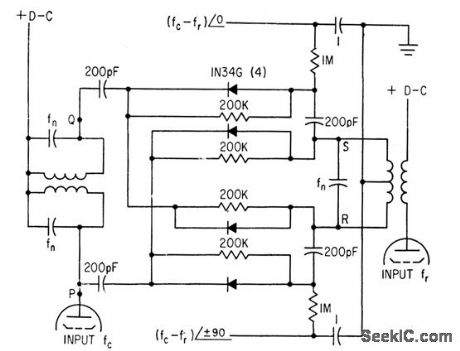
Used to lock crystal oscillator frequency to standard-frequency signals from WWV. Circuit mixes dock and WWV frequencies (fed to tubes at left and right) in Nygaard discriminator ar rangement, which delivers two outputs, each equal to difference frequency but differing 90°in phase. These output signals are amplified for synchronous motor that drives trimmer capacitor of crystal oscillator in servo loop that brings difference frequency to zero.-K.Nygaard, Atomic Clock Accuracy for Crystal Oscillators, Electronics, 33:46, p82-83. (View)
View full Circuit Diagram | Comments | Reading(1002)
TWO_TRANSISTOR_TRF_RADIO_RECEIVER_WITH_AUDIO_AMPLIFIER
Published:2009/7/17 3:28:00 Author:Jessie

This receiver allows you to select the gain of its 11 RF ramplifier by adjusting R4. (View)
View full Circuit Diagram | Comments | Reading(5457)
5_V_AND_±12_V
Published:2009/7/17 3:28:00 Author:Jessie
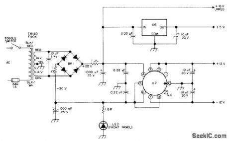
Also provides 18 unregulated for use with code regenerator driving automat Morse-code printer BR1 is Motorola MDA920-3 or HEP-R0802 bridge, LED is HP5082-4882 or HEP-P2000, U6 is LM341-5, MC7805, or HEP-C6110P. U7 is LM326H with TO5 finned clip-on heatsink, - H. Olson, CW Regenerator/Processor, 73 Magazine, July 1976, p 80-82. (View)
View full Circuit Diagram | Comments | Reading(2131)
ULTRASONIC_PEST_REPELLER_II
Published:2009/7/11 2:09:00 Author:May

A CD4011 Quad NAND gate acts as an oscillator, operating around 40 kHz. The small amount of filtering used modulates this with 120-Hz hum. The speaker is a small tweeter for hi-fi applications. (View)
View full Circuit Diagram | Comments | Reading(1502)
Servo_motor_power_amplifier
Published:2009/7/17 3:27:00 Author:Jessie

Servo motor power amplifier (courtesy Motorola Semiconductor Products Inc.). (View)
View full Circuit Diagram | Comments | Reading(1100)
HIGH_ACCURACY_CURVE_TRACER
Published:2009/7/11 2:09:00 Author:May
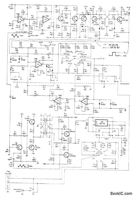
Can be used with any calibrated CRO, formatching and testing transistors or diodes by comparing performance curves. All opamps are 709C. Triangle wave generated by IC1-IC2 is fed to Schmitt trigget Q1-Q2, which generates square wave having transitions at zero voltagecrossings of input triangle. Q3 clamps square wave to 6.3 V P-P. Flipflop Q4-Q5 generates same square wave but at half the frequency of triangle wave. Combining square waves gives three-step staircase voltage having steps precisely in phase with zero signal crossings of triangle wave. T1 is UTC A-20 audio transformer, and T2 is Stancor P-6411 I5-W 1:1 isolation transformer. Article covers construction, alignment, and use, and gives circuit of suitable regulated supply operating from ±110 and ±6.3 V available in AN/USM-140C military version of Hewlett-Packard 170 CRO.-A. J. Klappenberger, An Accurate Solid State Component Curve Tracer, CQ, July 1974, p 20-24 and 82. (View)
View full Circuit Diagram | Comments | Reading(1115)
Timer_one_shot_with_zero_standby_power
Published:2009/7/17 3:26:00 Author:Jessie
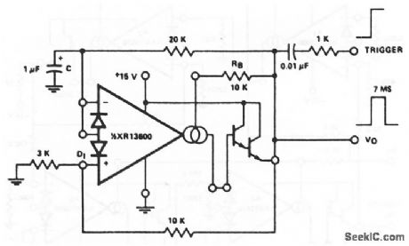
This circuit uses one section of an XR-13600 (Fig.11-1B) to form a timer or one-shot that draws no current from the supply until it is triggered. The trigger must be at least 2V, and the output is 7 ms with the values shown, EXAR Corporation Databook 1990 p 5-256 (View)
View full Circuit Diagram | Comments | Reading(630)
40_METER_DIRECT_CONVERSION
Published:2009/7/11 2:07:00 Author:May

Simple, foolproof circuit design uses discrete components mounted on printed-circuit board shaped to fit in oval herring can. Single 7-MHz RF stage and voltage-tuned VFO feed produgt detector Q2 that drives 2-stage AF amplifier having peak response at about 650 Hz for most comfortable CW listening. VFO uses Armstrong or tickler-feedback circuit, with CR1 and CR2 connected as voltage-variable-capacitance diodes. Zener regulator powers VFO circuit for good frequency stability Receiver will tune any 100-kHz segment of 40-meter band.-J Rusgrove,The Herring-Aid Five,QST,July 1976,p 20-23. (View)
View full Circuit Diagram | Comments | Reading(1260)
SOLID_STATE_REGENERATIVE_RECEIVER
Published:2009/7/17 3:26:00 Author:Jessie

You will need to modify the coil shown to use it with the regenerative receiver. Place a single layer of electrical tape around the bottom winding of the coil (L1); wind 6 turns of 19- or 20-gauge wire over the taped winding, leaving 4 pigtails. Tape the winding in place. Then connect the modified coil to the receiver circuit as shown in the figure. The two 2N3904 transistors are connected in a Darlington high-input-impedance circuit configuration to reduce loading of the tuned circuit. Potentiometer R2 controls the positive RE feedback. If the receiver seems dead or if only weak signals are heard, try reversing the leads on the six-turn feedback coil. (View)
View full Circuit Diagram | Comments | Reading(4573)
FIXED_CURRENT_REGULATOR
Published:2009/7/17 3:26:00 Author:Jessie

This ftxed 1-mA current source delivers a ftxed current to a load connected between Q1's collector and ground; the load can be anywhere in the range from 0 Ω to 14 Ω. The circuit is powered from a regulated 15-V supply, and the R1/R2 voltage divider applies a 14-V reference to R3. The op amp's output automatically adjusts to provide an identical voltage at the junction of R4 and R5. That produces 1 V across R5, resulting in an R5 current of 1 mA. Because that current is derived from Q1's emitter, and the emitter and collector currents of a transistor are almost identical, the circuit provides a fixed-current source. The output current can be doubled by halving the value of R5. (View)
View full Circuit Diagram | Comments | Reading(808)
ULTRASONIC_PEST_REPELLER_I
Published:2009/7/11 2:06:00 Author:May

An NE555 timer is used to generate an ultrasonic signal in the 20- to 65-kHz range. The speaker is a small piezoelectric tweeter with response above 20 kHz. These frequencies are said to be annoying to rats. mice. and insects. (View)
View full Circuit Diagram | Comments | Reading(1876)
Single_amplifier_VC0
Published:2009/7/17 3:26:00 Author:Jessie
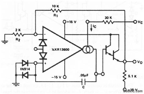
This circuit uses only one section of an XR-13600 (Fig.11-1B) to form a VCO. The remaining section can then be used for another purpose. EXAR Corporation Databook 1990 p 5-255 (View)
View full Circuit Diagram | Comments | Reading(566)
AF_LINE_TESTER
Published:2009/7/11 2:04:00 Author:May

Gives complete check of shielded twisted-pair cablein one operation, indicating short-circuits between conductors and providing positive continuity check of each conductor. Tester using polarity-sensitive bicolor LEDs is connected to one end of cable under test, and two-diode plug is patched in at other end. If cable is good, only green LEDs come on. If a conductor in cable is open, oneor both green LEDs will be off. One or both red LEDs will light for short between any combination of conductors or if cable is wired incorrectly. Signal diode types are not criticaL-W. L. Mahood, Testerfor Balanced Audio Lines, EDN Magazine, April 5, 1974, p 80 and 82. (View)
View full Circuit Diagram | Comments | Reading(825)
4_bit_look_ahead_carry_adder_using_an_MC10179_and_four_MC10180s
Published:2009/7/17 3:26:00 Author:Jessie
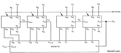
4-bit look-ahead carry adder using an MC10179 and four MC10180s (courtesy Motorola Semiconductor Products Inc.). (View)
View full Circuit Diagram | Comments | Reading(1637)
SIMPLE_WWV_CHECK
Published:2009/7/11 2:04:00 Author:May
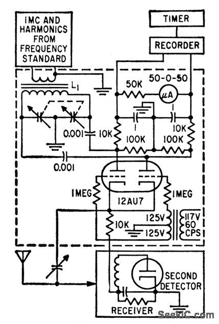
Permits making accurate check of local frequency standard quickly and easily by direct comparison with WWV signctls. Uses one receiver. Two signals, at0 and 180°, are obtained from local standard clock. Switch 12AU7 alternately connects one triode detector output and 0°signal simulta-neously to antenna, and then other triode detoctor output simultaneously with 180°signal.Doppler error is minimized by averaging hourly 3-minute readings over 8-hour period.Accuracy is one part in 100,000,000.-J. F.Brumbach, Fast WWV Check of Frequency Standard, Electronics, 32:13, p76-79. (View)
View full Circuit Diagram | Comments | Reading(681)
FM_IF_STRIP
Published:2009/7/17 3:25:00 Author:Jessie

View full Circuit Diagram | Comments | Reading(777)
COMMON_HOT_LEAD_REGULATOR
Published:2009/7/17 3:25:00 Author:Jessie

This circuit derives 5 Vdc from 2-AA cells-even at their end-life voltages of 1.05 V, and is approximately 80% efficient, providing 5 V at 4 mA from 2.1 V at 11 mA. IC1 is manufactured by Maxim Integrated Products, Inc. (View)
View full Circuit Diagram | Comments | Reading(584)
| Pages:783/2234 At 20781782783784785786787788789790791792793794795796797798799800Under 20 |
Circuit Categories
power supply circuit
Amplifier Circuit
Basic Circuit
LED and Light Circuit
Sensor Circuit
Signal Processing
Electrical Equipment Circuit
Control Circuit
Remote Control Circuit
A/D-D/A Converter Circuit
Audio Circuit
Measuring and Test Circuit
Communication Circuit
Computer-Related Circuit
555 Circuit
Automotive Circuit
Repairing Circuit