
Circuit Diagram
Index 780
TIL_TESTER
Published:2009/7/11 3:01:00 Author:May

Used to check quality, identify intemal sections, and identify terminals of unmarked TTL ICs. Operates from 5-VDC source, which should have current-limhed output for fuse protection against shorts. Used with ordinary CRO, for which horizontal and vertical lacks are shown on diagram. Article tells how eight different oscilloscope displays are interpreted, and gives procedure for identifying terminals of chip one by one as test probe is held on pins.-S.S.Smith, Jr., A TTL Tester, 73 Magazine, Oct. 1976, p 110-111. (View)
View full Circuit Diagram | Comments | Reading(764)
CMOS_KEYER_1
Published:2009/7/11 3:00:00 Author:May

Features include self-completing dots and dashes, dot and dash memofies, iambic operation, dot and dash insertion, and automatic character spacing, all achieved with low-power CM0S digital devices that are compatible with low-power (QRP) transceiver operation, as with Heathkit HW-7 transceiver. Will operate directly from a-15 V batteries of QRP transceiver, without regulation.-G. Hinkle, The aRP Accu-Keyer, 73 Magazine, Aug. 1975, p 58-60. (View)
View full Circuit Diagram | Comments | Reading(1840)
POWER_PEAK_METER
Published:2009/7/11 3:00:00 Author:May

Optical Electronics 5897 four-quadrant multiplier generates product of load voltage and load current, while 5030 peak sense-and-hold module holds peak power for display on panel meter or other readout. Applications include measuring peak power applied to transistor, motor, lamp, or squib. If power peak at particular moment is required, such as that of transistor failure or squib detonation, 5020 sample-and-hold module is used in addition to or in place of 5030. Hold command can be obtained from flip-flop connected for triggering by abrup(change in power level.- A Peak Reading/Sampled Reading Power Meter, Optical Electronics, Tucson, AZ, Appli-cation Tip 10083. (View)
View full Circuit Diagram | Comments | Reading(646)
CW_CALL_GENERATOR
Published:2009/7/11 2:58:00 Author:May

Basic CW identifier uses two gates of 7400 to form starting flip-flop of automatic message generator. Provides ad-iustable speed and tone, with up to 256 bits of storage in Harris H1256 PROM. IC2 is 555 astable MVBR providing clock signal for driving two 7493 4-bit binary counters that address PROM.When counters reach maximum address of 255, next clock count makes PROM restart at address 0. Each address turns on tone oscillator for one clock period, producing one dit. Three addresses in row turn on tone for three clock periods, producing one dah. Space between dits and dahs of same letter is equal to one dit, letter space is three dits, and word space is six dits (2 dahs). Thus,W takes nine addresses. Article describes operation in detail and tells how to modify circuit for use as RTTY message gen-erator.-R. B. Joerger, PROM Message Generatorfor RTTY, 73 Magazine, March 1977, p 94-98. (View)
View full Circuit Diagram | Comments | Reading(1327)
SYNCHRONIZING_33_MC_CLOCK_TO_300_PPS_TRIGGER
Published:2009/7/11 2:56:00 Author:May
Synchronizes crystal-controlled tran of of 3.3-Mc clock pulses to unrelaled sync trigger having nominal repetition rate of 300 pulses per second, to provide constant delay between end of sync pulse and first clock pulse.-P. Danzer, Synchronized, Crystal-Controlled Oscillcator, EEE, 12:5, p90. (View)
View full Circuit Diagram | Comments | Reading(469)
FAST_BREAK_IN
Published:2009/7/11 2:55:00 Author:May
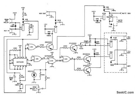
Permits operator to hear signals even between dots while calling DX station, so call can be stopped if DX station answers someone else. Timing circuit ensures that transmitter is not producing power when relays open, permitting use of small high-speed relays. K1-K4 are common reed relays. K5 should have contacts rated for 300 VAC at 500 mA.-A. Pluess, A Fast aSk System Using Reed Relays, QST, Dec. 1976, p 11-12. (View)
View full Circuit Diagram | Comments | Reading(553)
VIDEO_OP_AMP_CIRCUITS
Published:2009/7/11 2:54:00 Author:May
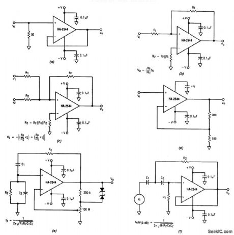
These 6 circuits use the Harris HA2544 op amp. Component values are obtained by using the equations in the figure.The HA-2544 can be used in any number of standard op amp configurations, including a voltage follower (a), an inverting amplifier (b), an inverting summer (g), a buffer amplifier with a gain of 10 (d), a Wien-bridge oscillator with zener diode adaptive feedback (e), and a second-order, high-pass active filter (f). (View)
View full Circuit Diagram | Comments | Reading(2362)
CODE_MONITOR
Published:2009/7/11 2:53:00 Author:May

Works with any transmitter, regardless of type of keying. Use any good PNP transistor. With NPN transistor, reverse connections to diode. Frequency of tone gets higher as resistance of 250K pot is reduced.Monitor is turned off at minimum resistance.Enough RF to operate monitor can be obtained simply by connecting it to chassis of receiver or transmitter.-J. Smith, Yet Another Code Monitor, 73 Magazine, Sept. 1971, p 58. (View)
View full Circuit Diagram | Comments | Reading(727)
KEYER_WITH_DOT_MEMORY
Published:2009/7/11 2:52:00 Author:May

Features include self-completing characters, exact timing of characters, and dot memory. Timing circuit uses 74121 mono MVBR U1, serving dot gen-erator and output stage U2A, dot memory U2B, and dash generator U3A-U3B. U2 and U3 are 7473 dual JK flip-flops. Length of timing pulse is iletermined by R1-G1, with R1 controlling speed of keyer. Pulse-width stability at all speeds is better than 5% between first and all following pulses. Dot memory U2B allows keying of dot at any time, even if dash has not yet been completed. Dot is held in memory and keyed out automatically after dash. Diodes are 1N914.-J. H. Fox, An Integrated Keyer/TR Switch, QST, Jan, 1975, p 15-20. (View)
View full Circuit Diagram | Comments | Reading(1607)
COLOR_BAR_GENERATOR
Published:2009/7/11 2:51:00 Author:May

IC5 generates RS-170 NTSC synch.IC1,IC2 and IC3 make up the red,green,and blue video signals that drive the videoencoder section of IC6 to make up the color bars. IC3 is an a÷2 counter that drives 4-bit counter IC1.Gates IC2a through IC2b formthe R,B,and G,Video signals.IC6 encodes these,plus synch,to form an NTSC video output signal,which appears at TP12. (View)
View full Circuit Diagram | Comments | Reading(3692)
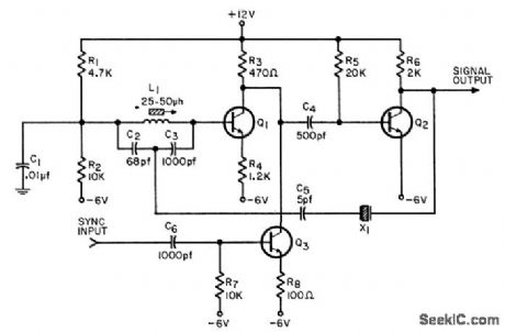
BFO_FOR_20_METERS
Published:2009/7/11 2:50:00 Author:May

Uses CA3045 transistor array, with U2A as series-tuned Clapp oscillator covering 7-7.2 MHz. Tuned emitter-follower U2B provides push-pull drive at 7 MHz to bases of push-push doubler U2C-U2D. Output of BFO is applied to product detector rather than to mixer of receiver. Audio signal from detector is frequency difference between BFO and incoming signal, typically 700 Hz for CW reception.Article covers construction and adjustment.-D. DeMaw, Understanding Linear ICs, QST, Feb.1977, p 19-23. (View)
View full Circuit Diagram | Comments | Reading(1869)
TRANSISTOR_BREAKDOWN_TESTER
Published:2009/7/11 2:49:00 Author:May

Simple circuit measures breakdown voltages of most types of small-signal and power transistors, reverse breakdown voltages of small power diodes, and zener diodevoltages. Two small 90V batteries in series provide power. R1 biases upper transistor into conduction. When voltage is applied to diode or transistor iunction under test, junction breaks down and current flows through R2. This makes lower transistor conduct, thereby dropping base voltage of upper transistor. R2 may be used to set breakdown current over wide range. Voltmeter reads breakdown voltage of junction, since drop across R2 is negligibly smalL-J. W. Brown, Simple Breakdown Voltage Meter, Wireless World, July 1973, p 337. (View)
View full Circuit Diagram | Comments | Reading(1910)
TONE_DECODER
Published:2009/7/11 2:49:00 Author:May

Decodes audio output of amateur radio receiver. Resulting audio tone burst corresponds to CW signal being received, with tone frequency varying with receiver tuning. Center frequency of NE567 phase-locked Ioop is ad justed with R1. Audio is translated into digital format of 1s and 0s, with tones for 0s. Output can be fed into computer for automatic translation of Morse code and printout as text,-W.A. Hickey, The Computer Versus Hand Sent Morse Code, BYTE, Oct. 1976, p 12-14 and 106. (View)
View full Circuit Diagram | Comments | Reading(0)
PORTABLE_CRYSTAL_TESTER
Published:2009/7/11 2:48:00 Author:May

Pierce oscillatorusing 2N4124, MPS3563, or HEP53 NPN transistor gives indication of crystal activity on M1, from upper HF range down to at least 455 kHz. Increase feedback capacitance with S1 for lower frequency, Choose sockets J1-J4 for types of crystals to be tested. With known good crystal, circuit can also be used for checking bipolar transistors, with S3 providing correct polarity. Diodes are 1N34A germanium or equivalent.-D. DeMaw and C. Greene, A Pair of Handy Testers, QST, May 1973, p 24-27. (View)
View full Circuit Diagram | Comments | Reading(1542)
FOUR_PHASE_12_MC_CLOCK
Published:2009/7/11 2:48:00 Author:May
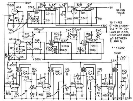
To minimize litter of synchronizing signals, fundomentcd frequency is chosen at one-eighth of dock rate or 1.5 Mc. Oscillator output is fed through two doubler stages and split into three channels, each having additional doubler followed by power amplifier, to provide low output impedance at any reasonable power level.-G.O. Olson, Design of High-Frequency Clock Pulse Generators, Electronics, 32:35, p56-57. (View)
View full Circuit Diagram | Comments | Reading(505)
PRODUCT_DETECTOR
Published:2009/7/11 2:48:00 Author:May

Designed for use in 40-meter CW direct-conversion receiver, in which oscillator input is from 3.5-4 MHz VFO. U1 is RCA CA3046 transistor quad. Circuit provides bias stabilization for constant-current transistor and some amplification of AF output. T1 is audio transformer.-A. Pharos, The CA3046 IC in a Direct-Conversion Receiver, QST, Nov.1973,p 45. (View)
View full Circuit Diagram | Comments | Reading(0)
VR_TUBE_CHECKER
Published:2009/7/11 2:47:00 Author:May

Increase output voltage of Variac gradually until VR tube fires, then read milliammeter and voltmeter. Good tubes will fire at their rated voltage and current values.-Circuits, 73 Magazine, May1977,p31. (View)
View full Circuit Diagram | Comments | Reading(830)
DIODE_CHECKER
Published:2009/7/11 2:46:00 Author:May
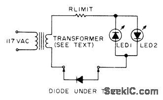
Requires only one resistor, two LEDs, and any small power transformer providing 3 to 25 VAC. If diode under test is open, neither LED lights, lf diode is shorted, LED1 lights on one half-cycle and LED2 on other half-cycle, so both appear lit continuously. If diode is good, LED1 will light if anode of diode is toward transformer, and LED2 will light for other polarity of diode. Choose resistor to limit current through LEDs to about 10 mA.-M. D. Kitchens, Ultra Simple Diode Checker, 73 Magazine, Oct. 1977, p 44-46. (View)
View full Circuit Diagram | Comments | Reading(495)
POCKET_SIZE_CRYSTAL_CHECKER
Published:2009/7/11 2:44:00 Author:May

Providesquick check of condition when shopping for used or surplus crystals Meter gives steady indieation at about half scale when test button is pushed, if crystal is oscillating properly.-Circults,73 Magazine, April 1977, p 164. (View)
View full Circuit Diagram | Comments | Reading(599)
CMOS_KEYER
Published:2009/7/11 2:43:00 Author:May

Draws only 0.4 mA on standby and 2 mA with key down if supply is 10 V. Will work properly with 4 to 15 V. Features include self-completing dots, dashes, and spaces, along with sidetone generator and built-in transmitter keying circuit. Ratio of dashes to dots is 3 : 1, and space has same duration as dot. Time base of keyer is generated by N0R gates U2C and U2D connected as class A MVBR. Frequency of oscillator is inversely linear with setting of R1.Inverter U3D buffers oscillator and squares its output. Flip-flop U6B divides frequency by2 and provides clock source with perfect 50% duty cycle. Once enabled, gates ensure completion along with following space. Article gives power supply circuit operating from AC line and 12-V battery.-J. W. Pollock, COSMOS IC Electronic Keyer, Ham Radio, June 1974, p 6-10. (View)
View full Circuit Diagram | Comments | Reading(884)
| Pages:780/2234 At 20761762763764765766767768769770771772773774775776777778779780Under 20 |
Circuit Categories
power supply circuit
Amplifier Circuit
Basic Circuit
LED and Light Circuit
Sensor Circuit
Signal Processing
Electrical Equipment Circuit
Control Circuit
Remote Control Circuit
A/D-D/A Converter Circuit
Audio Circuit
Measuring and Test Circuit
Communication Circuit
Computer-Related Circuit
555 Circuit
Automotive Circuit
Repairing Circuit